


8
20LK31M
20LK61M
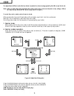
White Balance Adjustment.
1. Receive a good local channel.
2. Select the service adjustment "S12" and set the data
value to "00" to set the color level to the minimun.
You may skip this step, if you selected a B/W picture
or monoscope.
3. Alternately adjust the service adjustment data of
"S08" and "S09" until a good grey scale with normal
white is obtained.
4. Select the service adjustment "S12" and reset data
to obtain normal color level.
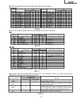
Sub-Picture Adjustment
1. Receive a good local channel.
2. Make sure the customer picture control is set to
maximum.
3. Enter the service mode and select the service
adjustment "S10".
4. Adjust the data value to achieve normal contrast
range.
Sub-Tint Adjustment
1. Receive a good local channel.
2. Set the customer tint control to the center of it’s range.
3. Enter the service mode and select the service
adjustment "S11".
4. Adjust "S11" data value to obtain normal fresh tones.
Sub-Color Adjustment
1. Receive a good local channel.
2. Make sure the customer color control is set to center
position.
3. Enter the service mode and select the service
adjustment "S12".
4. Adjust "S12" data value to obtain normal color level.
Sub-Brightness Adjustment
1. Receive a good local channel.
2. Make sure the customer brightness control is set to
center position.
3. Enter the service mode and select the service
adjustment "S13".
4. Adjust "S13" data value to obtain normal brightness
level.
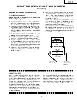
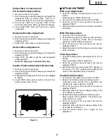
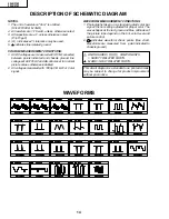
Figure B: Waveform for Screen Adjustment
Ë
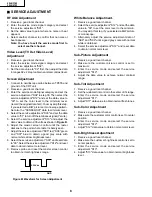
SERVICE ADJUSTMENT
RF AGC Adjustment
1. Receive a good local channel.
2. Enter the service mode signal category and select
the service adjustment "S01".
3. Set the data value to point where no noise or beat
appears.
4. Select another channel to confirm that no noise or
beat appears.
Note: You have to exit the service mode first to
select another channel.
Video Level (TV Det Video Level)
Adjustment
1. Receive a good local channel.
2. Enter the service mode signal category and select
the service adjustment "S02".
3. Set the data value to "02" first, then adjust the data
in ranges 02 ±2 step to obtain a normal contrast level.
Screen Adjustment
1. Connect to oscilloscope probe between TP855 and
ground of the CRT unit.
2. Receive a good local channel.
3. Enter the service mode Signal category and set the
service adjustment "S04" to step 30. Then select the
service adjustment "S12" and set the data value to
"00" to set the color level to the minimum level.
(record the original data first). You may skip this step,
if you selected a B/W picture or monoscope pattern.
Set also the "S05/S06/S07" data to minimum level.
4. Select the service adjustment "S03" and set the data
value to "01" to turn off the luminance signal (Y-mute).
5. Select the service adjustment "S13" and adjust the
data value to obtain 2.35 volts as shown in Figure B.
6. Adjust the master screen control until the raster
darkens to the point where raster is barely seen.
7. Adjust the service adjustment "S05" red, "S06" green
and "S07" blue to obtain a good grey scale with
normal white at low brightness level.
8. Select the service a adjustment "S03" and reset data
to "00". Select the service adjustment "S12" and reset
data to obtain normal color level.
9. Remove probe and reset the master screen control
to obtain normal brightness range.
2.35 Vdc
GND
Содержание 20LK31M
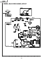
Страница 10: ...10 20LK31M 20LK61M 6 5 4 3 2 1 A B C D E F G H MODEL 20LK31M CHASSIS LAYOUT PWB A PWB B PWB C ...
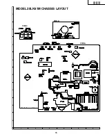
Страница 11: ...11 20LK31M 20LK61M 6 5 4 3 2 1 A B C D E F G H MODEL 20LK61M CHASSIS LAYOUT PWB A PWB B PWB C ...
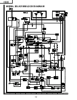
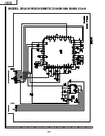
Страница 12: ...12 20LK31M 20LK61M 6 5 4 3 2 1 A B C D E F G H MODEL 20LK31M BLOCK DIAGRAM ...
Страница 13: ...13 20LK31M 20LK61M 6 5 4 3 2 1 A B C D E F G H MODEL 20LK61M BLOCK DIAGRAM ...
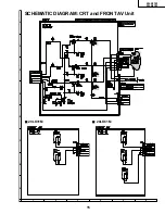
Страница 15: ...15 20LK31M 20LK61M 6 5 4 3 2 1 A B C D E F G H SCHEMATIC DIAGRAM CRT and FRONT AV Unit Ë 20LK61M Ë 20LK31M ...
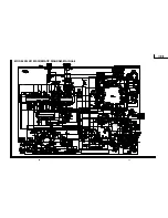
Страница 16: ...17 20LK31M 20LK61M 16 12 11 10 9 8 7 6 5 4 3 2 1 A B C D E F G H MODEL 20LK31M SCHEMATIC DIAGRAM MAIN Unit ...
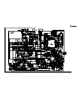
Страница 17: ...19 20LK31M 20LK61M 18 12 11 10 9 8 7 6 5 4 3 2 1 A B C D E F G H MODEL 20LK61M SCHEMATIC DIAGRAM MAIN 1 Unit ...
Страница 18: ...20 20LK31M 20LK61M 6 5 4 3 2 1 A B C D E F G H MODEL 20LK61M SCHEMATIC DIAGRAM MAIN 2 Unit ...
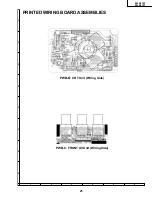
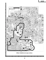
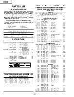
Страница 20: ...22 20LK31M 20LK61M 6 5 4 3 2 1 A B C D E F G H PWB A MAIN Unit Wiring Side ...
Страница 21: ...23 20LK31M 20LK61M 6 5 4 3 2 1 A B C D E F G H PWB A MAIN Unit Component Side ...


