


8
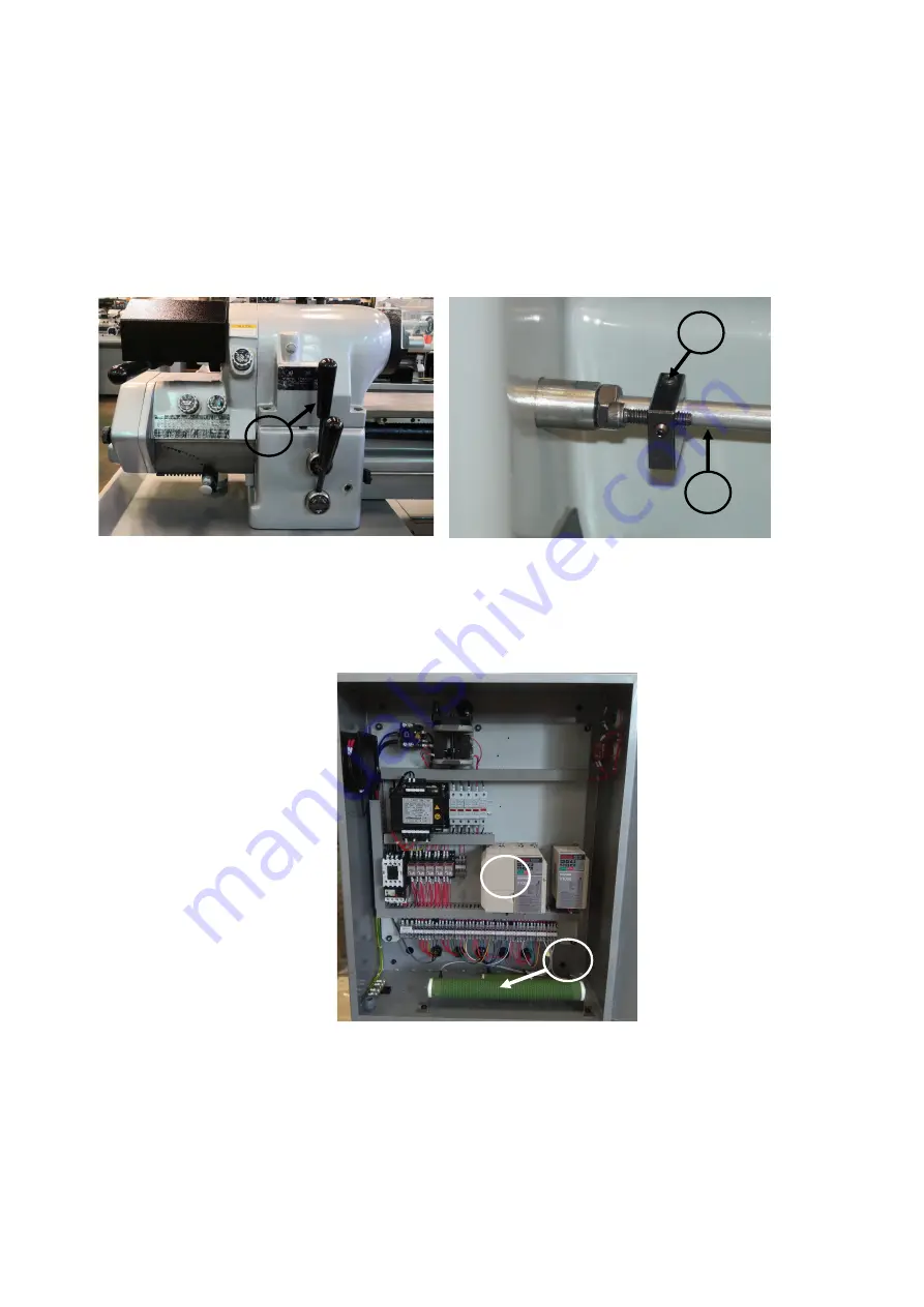
G.) AUTOMATIC THREAD LENGTH CONTROL
When threading into a blind hole or to a shoulder without a thread relief. The lead screw
half nut if engaged at the start of the threading work is completed. Left or right hand threads
are controlled by Control lever “D” (Figure 15), the lever is joined with the control bar “B”
(Figure 16). When the carriage touches the adjusting screw “S” (Figure 16) of the length
control bar, it will push the lever “D” (Figure 15) to “STOP” position, and make the lead
screw stop. For method of threading cut, please see Page 10, QUICK ACTING.
H.) SPINDLE BRAKE
Inverter unit “E” is used to perform dynamic braking. In addition, discharge resistor “C”
shortens braking time (Figure 17).
Figure 15-Control speed and Direction
Figure 17-Control Unit
C
Figure 16-Thread Length Control
D
S
B
E
Содержание 1118H
Страница 1: ...OPERATION MANUAL PARTS LIST Machine Model No Machine S N 1118H ...
Страница 34: ...31 HEADSTOCK ASSEMBLY ...
Страница 38: ...35 THREADING GEAR BOX ASSEMBLY ...
Страница 39: ...36 ...
Страница 40: ...37 ...
Страница 41: ...38 ...
Страница 42: ...39 ...
Страница 43: ...40 ...
Страница 45: ...42 COLLET CLOSER ...
Страница 47: ...44 BED ASSEMBLY ...
Страница 49: ...PADESTAL ASSEMBLY 46 ...
Страница 51: ...48 CARRIAGE ASSEMBLY ...
Страница 53: ...50 GEAR BOX OF CARRIAGE ASSEMBLY ...
Страница 56: ...53 CROSS AND COMPOUND SLIDE ASSEMBLY ...
Страница 58: ...A C MOTOR POWER FEED CONTROL ASSEMBLY 55 ...
Страница 60: ...CLUTCH ASSEMBLY 57 ...
Страница 62: ...59 A C MOTOR ASSEMBLY ...
Страница 64: ...61 VARIABLE SPEED CONTROL BOX ASSEMBLY ...
Страница 66: ...TAILSTOCK ASSEBMLY 63 ...
Страница 67: ...1118H 5HP 220V ...