PROTECTIVE PLATE TGB BLADE 600 LTX
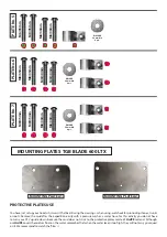
The set of protective plates is made of a specially designed material. The protective plate, after taking even a large impact
force, accumulates them and does not deform the material, returning to its original form. High quality and repeatability
of production using the latest CNC technologies ensure ease and speed of assembly. Each plate is precisely adapted to
a given quad model at the design stage, which guarantees the exact fit of the elements to the structure. The kit includes
all the necessary elements, there is no need for additional modifications or drilling. Read the instructions before starting
the assembly. The assembly instructions are for the TGB Blade 600 LTX model only and cannot be used with other quad
models. The surface of the material is easy to clean. Another advantage is easy access to changing fluids without the need
to disassemble the plates. It is very light compared to other record makers.
INSTALLATION KIT
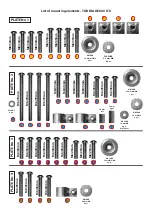
It contains a set of protective plates with mounting elements (screws, mounting plates, washers, sleeves, nuts and additional
fastening elements) each of the plates has its own individual installation kit, packed in separate bags for each of the plates.
It is recommended to unpack the installation elements only for the currently installed plates, which will avoid mistakes
and mixing of the fixing elements. Re-sorting can be done according to with a list of mounting items attached.
TOOLS REQUIRED FOR ASSEMBLY
Allen key No. 4 (for M6 screws) and 5 (for M8)
DIRECTIONS
Screw the bolts fastening the plates to the structure elements, which will enable their position to be adjusted, and then tighten
them sensitively, without breaking the thread. After driving a dozen or so kilometers, check whether the mounting screws have
been properly tightened, any loose ones must be tightened, also with feeling :-)
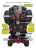
The figure shows the orientation of the taps, bottom view. To properly connect the protection plates to the frame structure, the catches should settle from the top of the structural tubes,
this applies to all connections of this type specified in the diagram. The hooks and pipes are marked in red along with their orientation.
Sufficient space for hands and tools allows the mounting of catches of the control arm covers at the marked points, without disassembling any other components.
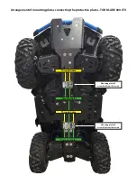
Front control arm. EXAMPLE OF
MOUNTING
(Fig. 1)
Rear transverse control arm.
EXAMPLE OF MOUNTING
(Fig. 2)


