Shakmat Dual Dagger Скачать руководство пользователя страница 8

www.shakmat.com 

07/19

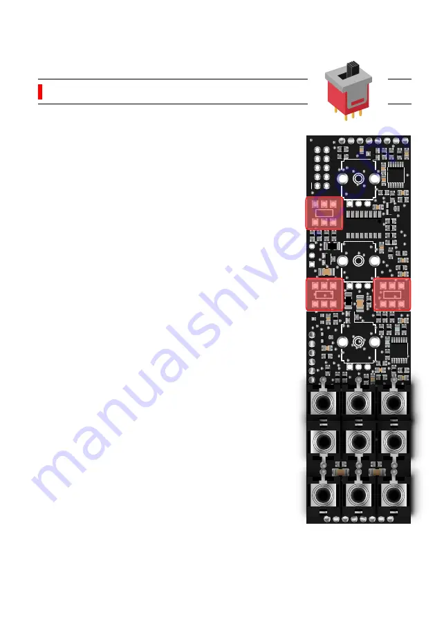
Place and solder the 3 slide switches. Be sure 

to lay them flat on the PCB when soldering. 

We recommend you only solder one of the pin, 

check alignement and if you are satisfied with 

you placement, solder the remaining pins.


5.1.2 

Slide switches (x3) 


   P2

Содержание Dual Dagger

Страница 1: ...Shakmat DualDagger BuildingGuide 12HP Eurorack Module Built designed in E U www shakmat com...

Страница 2: ...ader 2x5 pin 5 2 1 Male headers 1x3 pin Bottom PCB assembly 6 1 Front 6 1 1 Trimmers 50k 6 1 2 Trimmers 1k Finish Calibration 8 1 Range adjustment 8 1 1 Range adjustment using a multimeter 8 1 2 Range...

Страница 3: ...bly process in the most practical and comprehensive way If by any chance there is a missing damaged part in your kit or if you have any suggestion feel free to contact us via shakmat com The assembly...

Страница 4: ...al potentiometer nuts Pack 2 4x 1K trimmer 2x 8 pin male header 2x 8 pin female header 3x Slide switch 9x Jack connectors 9x Jack connectors nuts 2x M3 metal screws 2 Component list necessary tools Pa...

Страница 5: ...com 04 19 3 PCB details Top PCB Front back Bottom PCB Front back 12V GND VHPR VHPL INITHPR FHPr RHPr FLpr RLPl INITLPR VLPL VLPR RESO LOW HP_L HP_R GND_2 RLPr CVHPl CVHPr CVLPl CVLPr HI 330 CFT 0G2 3...

Страница 6: ...e all the headers with their mate Then place the female part on the bottom PCB and the male part through the top PCB Then assemble the two boards toghether and proceed to the soldering You will first...

Страница 7: ...the 9 jack connectors Be sure to lay them completely flat on the PCB before solde ring If those jacks aren t perpendicular the front panel will be very hard to mount If one of the jacks is not perfec...

Страница 8: ...lder the 3 slide switches Be sure to lay them flat on the PCB when soldering We recommend you only solder one of the pin check alignement and if you are satisfied with you placement solder the remaini...

Страница 9: ...om sitting properly Use some small sharp cutting pliers for this task Then place the 3 potentiometers on the PCB Mount the front panel and tighten the potentio meters nuts lightly this will ensure a p...

Страница 10: ...2 www shakmat com 09 19 Place the power header the short pin side in the holes and solder only one of the pins Check the alignment and correct if necessary Then once your component is upright and flat...

Страница 11: ...e recommend you only solder one of the pins check the alignment If necessary reheat your soldered point and simultaneously press the plastic part of the header against the PCB until it s flat Take off...

Страница 12: ...CB assembly Detach the two PCBs and continue with the bottom PCB Place solder the 6 50k trimmers one by one Be careful to put them in the right direction The little adjustment screw must be pointing o...

Страница 13: ...little adjustment screw must be pointing outward Potentiometer nuts x3 P1 7 Finish You re almost done The last thing to do is to mount the front panel and place the nuts on the potentio meters and ja...

Страница 14: ...mper at the back of the module to the HI postion Connect the negative probe of your multimeter to a ground point with an alligator clip clip to the sleeve part of a jack connector patch cable connecte...

Страница 15: ...ch must be off and the HPF potentiometer at noon The HP1 trimmer on the diagram below sets the range of the first highpass filter Listen to OUT 1 you should hear the filter auto oscillate Play on 3 oc...

Страница 16: ...oward the right The HPF resonance switch must be off and the LPF potentiometer at noon The LP1 trimmer on the diagram below sets the range of the first lowpass filter Listen to OUT 1 you should hear t...

Страница 17: ...imum possible attenuation Do the same for OUT 2 using the B trimmer 8 2 CV rejection adjustment 8 2 1 Highpass All the switches must be off Turn the LPF HPF potentimeters fully counter clockwise Patch...

Страница 18: ...set HP trimmer until you hear the very same frequency on the two outputs 8 3 Offset adjustment 8 3 1 Highpass Turn the HPF potentimeter fully counterclockwise and the RES potentiometer fully clockwise...

Страница 19: ...www shakmat com...

Отзывы: