background image

2

2.3 Ratio Table

2.4 Ratio Set

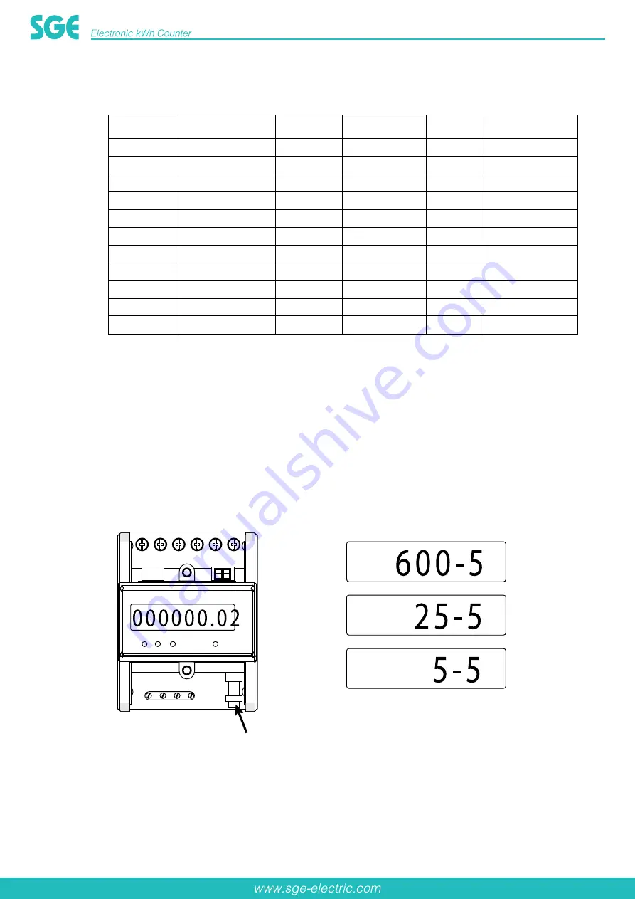
Display the current ratio about 2 seconds when turning on the power, the default ratio is 5/5, it will display
the power after 2 seconds. Press SET button if you need set CT ratio (see figure 1), the ratio will display
25/5, 40/5, 50/5, 60/5, 75/5, 60/5, 100/5, 120/5, 120/5, 200/5, 250/5, 300/5, 400/5, 300/5, 600/5, 800/5,
800/5, 1200/5, 1500/5, 1600/5, 2000/5, 1600/5, 3000/5, 4000/5, 4000/5, 6000/5, 5/5. (see figure 2)
In order to confirm a variable ratio, press the button for 30s until LCD displays initial energy. In this case
the variable ratio has been fixed and not able to modify any more.
Note: the button is inside the hole, we suggest you to use auxiliary tool that could touch the inside button
when set the ratio.

Fig.1

Fig.2

CT ratio

Energy display

CT ratio

Energy display

CT ratio

Energy display

5/5

000000.00

75/5

0000000.0

800/5

00000000

25/5

000000.00

80/5

0000000.0

1000/5

00000000

40/5

000000.00

100/5

0000000.0

1200/5

00000000

50/5

000000.00

120/5

0000000.0

1500/5

00000000

60/5

000000.00

150/5

0000000.0

1600/5

00000000

200/5

0000000.0

2000/5

00000000

250/5

0000000.0

2500/5

00000000

300/5

0000000.0

3000/5

00000000

400/5

0000000.0

4000/5

00000000

500/5

0000000.0

5000/5

00000000

600/5

0000000.0

6000/5

00000000

SET Button

Содержание SGE-353-1Y-10100M

Страница 1: ......

Страница 2: ...62053 21 Frequency 50 60Hz Impulse constant 12000imp kWh Display LCD 6 2 Power consumption 2W 10VA Starting current 0 002Ib Working Temperature 20 55 Storage Temperature 25 70 Working voltage 0 9 1 1...

Страница 3: ...this case the variable ratio has been fixed and not able to modify any more Note the button is inside the hole we suggest you to use auxiliary tool that could touch the inside button when set the rati...

Страница 4: ...dication of B Phase C Power Indication of C Phase D Impulse Output Material Case Grey flame resistant ABS Terminal cover Grey flame resistant ABS Base Bottom Grey flame resistant ABS 4 Display 5 Conne...

Страница 5: ...firmed by yourself fixed them in the location which are waiting for installation Put the meter into the upper Din Rail then push down the clip in the meter bottom see Fig 3 After the bottom of the met...

Страница 6: ...Fig 6 is after installation Fig 6 Making the connection according to the wiring diagram see Fig 7 Fig 7 After connection use lead sealing to seal terminal cover see Fig 8 Fig 8...

Страница 7: ...power distribution system The temperature for the data listed in the above table is 35 the safe carrying capacity value for the wire on single coved 8 8 8 8 Safety Instructions Information for Your O...

Страница 8: ...ed personnel in the manual Subject to technical modifications without notice General Warning After removing the packaging make sure the integrity of the unit If in doubt don t use the equipment and co...

Отзывы: