background image

18

  │ 3 Using the system

Various filter limits are available for adjusting the bandpass. The 

bandpass must be at least 300 Hz wide.

Information about the available filter limits can be found in 

sec-

tion 6.2.1.1.

3.4.2.2 

Activating the notch filter

When the notch filter is activated, the mains frequency (50 Hz or 

60 Hz) is filtered out. This eliminates the influence of current-car

-

rying lines on the noise.

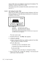
Fig. 12: 

Filter 

view 

Top right:  

notch filter (

here:

 50 Hz) 

Bottom left:  lower filter limit (

here:

 500 Hz) 

Bottom right:  upper filter limit (

here:

 3000 Hz) 

The symbol for the upper filter limit is inverted, which means that 

this filter limit can be adjusted.

The main view is open.

1.  Press the Filter key. The 

Filter

 view appears.

2.  Change the settings.

a) Keep pressing the Enter key until the symbol in front of the 

filter you wish to change is inverted.

b) 

For the filter limits:


Press the Up key to increase the value.


Press the Down key to lower the value.

For the notch filter:


Press one of the arrow keys to change the setting.

3.  Press the Filter key to apply the settings. The receiver will 

switch back to the main view.

Содержание AQUAPHON AF 50

Страница 1: ...02 09 2019 a 107762 en AQUAPHON AF 50 receiver Operating Instructions...

Страница 2: ...w keys Up key Fig 1 Receiver AF 50 viewed from various angles Down key Activation key Display Filter key Menu key Enter key Belt clip Headphone socket Connection for microphone search coil Charging so...

Страница 3: ...level bar Current minimum noise level marker Minimum noise level last but one Filter level Battery symbol wireless headphones Hearing protection level Volume Current minimum noise level last Hz Fig 3...

Страница 4: ...warnings in this document A WARNING Risk of personal injury Could result in serious injury or death A CAUTION Risk of personal injury Could result in injury or pose a risk to health NOTICE Risk of dam...

Страница 5: ...Activation key 8 2 4 3 Display of the results in the main view 9 2 4 4 Power supply 11 2 4 5 UM 50 universal microphone 12 2 4 6 SK 3 search coil 13 2 5 Differences between applications when locating...

Страница 6: ...ce 28 5 1 Charging the batteries 28 5 1 1 Charging the batteries in the case 28 5 1 2 Charging batteries individually using the AC DC adapter or vehicle cable 29 5 2 Handling faulty lithium ion rechar...

Страница 7: ...st of our knowledge The original German version is authoritative Right of reproduction No part of this document may be edited duplicated or circulated in any form without the express consent of Herman...

Страница 8: ...e The appropriate specialist knowledge is required for using this product 1 4 Safety information This product was manufactured in keeping with all binding legal and safety regulations The product is s...

Страница 9: ...during transport and when working Always adequately cordon off the work area When you are wearing headphones you are not fully aware of ambient noise Be especially vigilant especially in environ ments...

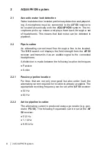
Страница 10: ...located The SK 3 search coil displays the field strength from the AF 50 receiver and transmits it as an audible signal to the connected headphones A distinction is made between the following location...

Страница 11: ...e when the user slips off the contact point using a microphone Hearing protection is activated when the predefined hearing pro tection threshold is exceeded When the noise from the source of interfere...

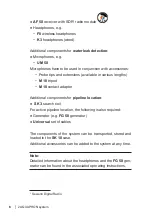
Страница 12: ...10 tripod M 10 contact adapter Additional components for pipeline location SK 3 search coil For active pipeline location the following is also required Generator e g FG 50 generator Universal set of c...

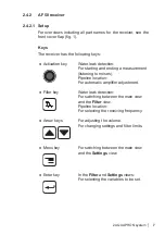
Страница 13: ...urement listening to noises Pipeline location For automatic amplifier adjustment Filter key Water leak detection For switching between the main view and the Filter view Pipeline location For selecting...

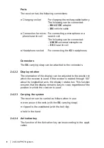
Страница 14: ...attached to the connectors 2 4 2 2 Display rotation The orientation of the display can be adjusted to the position in which the receiver is used If the receiver is rotated through 180 about its longi...

Страница 15: ...lifier adjustment sec tion 3 5 3 2 4 3 Display of the results in the main view The main view on the display differs depending on the applica tion Water leak detection Noise levels are measured during...

Страница 16: ...phical and numerical noise level display for water leak detection Top current noise level bar and current minimum noise level marker in bar Middle current minimum noise level here 1248 Right 1 previou...

Страница 17: ...ging the rechargeable battery can be found in section 5 1 NOTICE Risk of damage when changing the lithium ion battery There are parts in the receiver that can be damaged mechan ically or by electrosta...

Страница 18: ...sories are available for the UM 50 universal microphone Probe tip usually with extensions M 10 tripod M 10 contact adapter A CAUTION The UM 10 contact adapter for the UM 50 universal mi crophone conta...

Страница 19: ...icrophone is connected the receiver automat ically switches to water leak detection To listen to noises you must start a measurement During the measurement the current noise level is displayed both nu...

Страница 20: ...K 3 search coil must be used for pipe location There are no other accessories attached to the search coil 3 2 Starting up the system To start up the system perform the following steps in any order Con...

Страница 21: ...or the wireless head phones will appear in the main view Fig 9 F8 wireless headphones ready for use battery symbol for wireless headphones visible 3 2 2 2 K3 headphones The K3 headphones are connected...

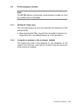
Страница 22: ...ase the volume Information about hearing protection and hearing protection thresholds can be found in section 4 5 and section 4 6 3 4 Performing water leak detection 3 4 1 Starting and ending a measur...

Страница 23: ...elow the hearing protection threshold again the symbol appears with out a cross through it No measurement is in progress because the measurement was not started correctly Check the operating mode sett...

Страница 24: ...Hz Bottom left lower filter limit here 500 Hz Bottom right upper filter limit here 3000 Hz The symbol for the upper filter limit is inverted which means that this filter limit can be adjusted The main...

Страница 25: ...eiving frequency must correspond to the frequency of the energized line Keep pressing the Filter key until the receiving frequency cor responds to the transmitting frequency of the generator 3 5 2 Usi...

Страница 26: ...proaches the line and reaches the maximum level when directly above it The maximum method is well suited to preliminary detection To use the maximum method Hold the SK 3 search coil as fig 13 shown in...

Страница 27: ...g reduced Hz Fig 14 Display during automatic amplifier adjustment Right symbol Wait Bottom symbol for headphones crossed out The receiver is switched on and the SK 3 search coil is con nected For auto...

Страница 28: ...settings can be restored at any time The settings are changed in the Settings view LIGHT ACTIVATION RESET DISPLAY MUTE PROTECT 85 Fig 15 Settings view 4 2 Backlight LIGHT The receiver display feature...

Страница 29: ...ivation key Hold mode Toggle mode Information about the operating modes can be found in sec tion 2 4 2 4 Changing the ACTIVATION setting The system is ready for use The display shows the main view 1 P...

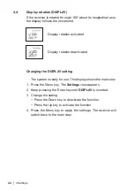
Страница 30: ...ted Changing the DISPLAY setting The system is ready for use The display shows the main view 1 Press the Menu key The Settings view appears 2 Keep pressing the Enter key until DISPLAY is inverted 3 Ch...

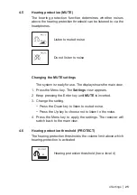
Страница 31: ...view 1 Press the Menu key The Settings view appears 2 Keep pressing the Enter key until MUTE is inverted 3 Change the setting Press the Down key to listen to muted noise Press the Up key to choose not...

Страница 32: ...protection will only activate with very loud noises This means that there is little protection for the hearing Always adjust the hearing protection threshold to the current situation Set the hearing p...

Страница 33: ...Restoring settings to factory settings An overview of the factory settings can be found in Sect 6 2 Restoring settings to factory settings Note The settings are reset immediately and with no further...

Страница 34: ...emperature returns to within the per mitted range There are two ways of charging the components all of the components simultaneously in the SK 10 case each component individually using the AC DC adapt...

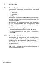
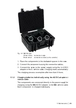
Страница 35: ...les 3 Connect the case to the power supply using the L AC DC adapter or the L vehicle cable Charging starts automatically The charging process is complete after less than 6 hours 5 1 2 Charging batter...

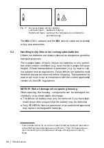
Страница 36: ...s subject to strict regulations Faulty lithium ion batteries must therefore always be removed before shipping Transportation by road or rail must occur in compliance with the current applicable versio...

Страница 37: ...ed mechan ically or by electrostatic discharge when removing the battery It is essential to read section 5 2 and section 5 2 1 before re moving the battery Avoid electrostatic discharges at all costs...

Страница 38: ...sitive to mechan ical and chemical stress Always use a clean soft cloth to clean the display surface Never use cleaning agents containing aggressive constituents e g acidic or abrasive constituents to...

Страница 39: ...ertificates FCC CE IC MIC Features Display 2 FSTN display 240 128 pixels LED backlight Processor DSP 16 bit Operation membrane keypad with 5 keys 1 activation key Operating conditions Operating temper...

Страница 40: ...3000 4000 8000 Hz notch filter 50 Hz 60 Hz off locating mode with SK 3 50 60 512 1100 9950 Hz Sampling rate 16 bit 48 kHz Indication range 0 1999 digits Data transmission Transmission frequency 2 408...

Страница 41: ...ng conditions Operating temperature 20 70 C Storage temperature 20 70 C Protection rating IP68 Permitted operating envi ronments outdoors in building Non permitted operating environments in aggressive...

Страница 42: ...sting the bandpass The bandpass must be at least 300 Hz wide Lower filter limit Upper filter limit 0 Hz 300 Hz 30 Hz 500 Hz 60 Hz 850 Hz 120 Hz 1000 Hz 250 Hz 1250 Hz 500 Hz 1500 Hz 2000 Hz 3000 Hz 40...

Страница 43: ...vated Hold mode Display rotation activated Do not listen to noise PROTECT 85 Hearing protection threshold level 4 Bandpass Lower filter limit Upper filter limit 0 Hz 4000 Hz Notch filter Symbol Notch...

Страница 44: ...e system Please contact our SEWERIN sales department for further information 6 4 Declarations of conformity Hermann Sewerin GmbH hereby declares that the A 50 receiver fulfils the requirements of the...

Страница 45: ...24 Display rotation 8 E Enter key 7 F Factory settings 27 37 Filter key 7 G Generator 4 H Headphone socket 8 Hearing protection 5 25 Hearing protection threshold 25 levels 26 Hold mode 9 L LIGHT 22 L...

Страница 46: ...rechargeable battery RESET 27 S Setting backlight 22 display rotation 24 hearing protection 25 hearing protection threshold 25 operating mode 23 SK 3 search coil 13 System F8 wireless headphones 15 K3...

Страница 47: ...ower Avenida Sur del Aeropuerto de Barajas 28 Of 2 1 y 2 2 28042 Madrid Espa a Tel 34 91 74807 57 Fax 34 91 74807 58 www sewerin es info sewerin es Sewerin Portugal Lda Rua do Senhor dos Milagres 16 2...

Отзывы: