


Operating Instructions – MOVIFIT® FDC
137
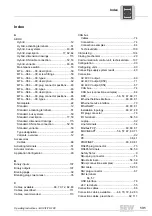
Index
Y
Y adapter ...............................................................77
0 ... 9
24 V terminals, connection ....................................55
Содержание MOVIFIT FDC
Страница 2: ...SEW EURODRIVE Driving the world...
Страница 137: ...Operating Instructions MOVIFIT FDC 137 Index Y Y adapter 77 0 9 24 V terminals connection 55...
Страница 138: ......
Страница 139: ......