


ST–III Series Power Supplies
USER INSTRUCTIONS
3. Flashing 1s ON, 1s OFF, with no battery connected the power supply may be in hiccup
mode which will cause the indication to flash with random duty cycle and frequency.
4. Fault Led= Solid On, All other leds = OFF, irrespective of actual mains or LVD status.
Auxiliary Power Input:
The power supply terminal “Aux In +VE” provides an alternative option
for powering of the load and float charging of the batteries when mains voltages are not present.
This input is to be powered by a suitable +12V system. (i.e. CAR). The voltage of the auxiliary
power source should not exceed 14.8 volts.
When operating via the external input, current and voltage control for the battery must be provided
from the external source. The ST20-II/35-II does not provide battery current limit or voltage control
when operating in this configuration. Trickle Charge is still functional when powered through
“Aux In +VE” terminal of power supply.
Suitable fuse protection must be provided for this input. A fuse rating not exceeding 20 Amps for
ST20-II and 30 Amps for ST35-II must be used.
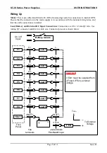
Solar power should be connected directly across the battery terminals with a voltage regulator in
series. A solar panel voltage regulator with maximum output voltage not exceeding 14.8 volts must
be used at all times. Failure to use a voltage regulator may result in power supply damage.
Generator 12 volt outputs should not be connected across battery terminal whilst battery is
connected to power supply or connected to the “Aux In +VE” terminal of power supply. Serious
power supply damage or internal explosion may occur. If a flat 12 volt battery has to be charged
using the generators 12 volt output, it should first be disconnected from the power supply. Once
battery has being charged it can then be reconnected to power supply.
Power supply unit should only be powered from either 240VAC mains or Auxiliary Power
(Auxiliary Power also includes solar power) but
not both
. Failure to do so may result in damage to
power supply.
Protection:
the power supply provides automatic protection for overload including short circuit,
over-voltage, over-temperature and reverse connected battery. In such instances the Fault indicator
will illuminate and the power supply will shut down. It will attempt to automatically restart every 5
seconds until such case that the fault is removed.
Fusing:
Each load circuit and the battery have been fused to provide fault protection and
discrimination. Refer to servicing section for maximum fuse ratings.
CAUTION:
This appliance is
not
intended for use by young children or infirm persons without supervision.
Young children should be supervised to ensure that they do not play with the appliance.
In order to avoid hazard when the supply cord becomes damaged, the cord must only be replaced by
the manufacturer or its service agent or similar technically qualified person.
Power supply unit should only be powered from either 240VAC mains or Auxiliary Power
(Auxiliary Power also includes solar power) but not both. Failure to do so may result in damage to
power supply.
Page 3 of 11
Issue D


