background image

D

Содержание T-GPS-300

Страница 1: ......

Страница 2: ...nchronisation Time synchronization synchronizing the electrical parameters such as event recorder disturbance recorder fault recorder and sequential event recorder PLC s data acquisition system and other intelligence or RTU remote terminal unit b Instrumentation Synchronisation Intelligence instrumentation PLC S DC S DAS SCADA and other intelligence RTU S c Networking of Computers Various computer...

Страница 3: ... power monitored and can be connected to computer for report generation WATT VAR display to many location similar to slave clock with large display for difference viewing f Calibration for frequency With advantage of atomic clock time we convert various frequencies and they are synthesized to give a very stable frequency available at all times traceability to national standard can be used to calib...

Страница 4: ...to inform you that our products are approved by various consultant agencies to name important companies such as NTPC Power grid EIL TCS Tata power BSES Reliance power GAIL and other consultancy also In case if you can inform us as your consultant we are glad to take an approval to enable yourself to use our equipment for your projects Yours faithfully For SERTEL ELECTRONICS PVT LTD R GOPALAN CHIEF...

Страница 5: ...R 18 SLAVE DISTRIBUTION AMP 19 SLAVE CLOCK BOOSTER UNIT 20 OPERATION 21 GPS MASTER CLOCK SLAVE CLOCK SYSTEM 22 FEATURES OF GPS RECEIVER 23 GPS RECEIVER LOCK UNLOCK 24 SERTEL MASTER CLOCK A B INTENDED 25 MASTER CLOCK OPERATION PROCEDURE 26 TO SET IN DATE 27 TO SET IN TIME 28 REDUNDANT COMPARATOR UNIT 29 RS 232 BH 232 OUTPUT FORMAT 30 RS 232 SEPL 232 OUTPUT FORMAT 31 RS 232 002 RS 232 OUTPUT FORMAT ...

Страница 6: ...on h Power supply A B and Diode Oring i Slave clock connection j Signal booster with Slave clock connection k Supply voltage ferule connection l Contact output ferule connection III Assembling lay out a GPS Receiver b Master A B c Comparator unit d RS 232 output unit e Pulse output unit f Signal conditioner IRIG B g Diode oring unit h Power supply IV PCB LAY OUT V Circuit diagram VI TEST CERTIFICA...

Страница 7: ...ium oscillation whose accuracy is comparable to Inter national Atomic Time GPS Receiver collects the data from GPS Satellites and out puts a time base pulse 1PPS every second in precise synchronisation with UTC IST Each 1PPS Pulse is accompanied by a Serial Data packet output A real time data comprising of Year Month Date Hour Minute and Second which is a time stamp for that pulse This output is u...

Страница 8: ...GNAL CONDITIONER FOR a RS 232 OUTPUT Signal conditioner b PULSE OUTPUT Signal Conditioner c IRIG B OUTPUT Signal Conditioner d TCP IP OUTPUT Signal Conditioner e TCP IP ON NTP OUTPUT Signal Conditioner f BCD OUTPUT Signal Conditioner 6 POWER SUPPLY A B CHARGER 7 DIODE ORING UNIT 8 LINE DRIVER RECEIVER 9 SLAVE CLOCK 10 SLAVE CLOCK SIGNAL BOOSTER 11 FULL WIRED PANEL ...

Страница 9: ...xial ratio 5 dB Co axial cable Low Loss Coaxial Cable 0 33 dB metre 100 metre along with matching connection Connector TNC N Connector Total gain Over 30 dB Noise figure Less than 2 6dB Supply Voltage 5 V DC internal supply Operating Temp 30 to 80 Deg C Storage Temp 40 to 85 Deg C Mounting Wall mounting ...

Страница 10: ...4 ...

Страница 11: ... O P Connectors RS 232 1PPS 9 Pin D Connector Front Panel LCD Display To show Required Data And Status and number of satellites valid data LED Back Panel 24 V input connector Fuse On Off switch RS 232 1 PPS output 9 Pin D connector Alarm contact terminal Supply Voltage 24V Supply from redundant Diode Oring unit Environments Temp 0 50 deg cen RH Up to 95 non condensing Mounting To suit Standard 19 ...

Страница 12: ...6 ...

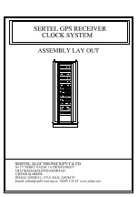
Страница 13: ...32C GPS Receiver I P Connectors D connector 9 pin for RS232 and 1 PPS Outputs Isolated output to Redundant comparator Clock O P Connectors 9 pin D connector for Signal output to Redundant Comparator unit Supply Voltage 24V supply from Diode Oring unit Environment a Temp 0 50 Deg C b RH 0 90 Non condensing Front Panel Display Toggle S W Date Time Thumb wheel Stn Push Button S W ENTER Lock S W with ...

Страница 14: ...8 ...

Страница 15: ...nditioner d Data RS232 Output to TCP IP TCP IP ON NTP Output Signal Conditioner e Differential Pulse to Slave Clock Slave Distribution amp f Alarm Contact output for Master signal fail O P Connectors a 9 pin D connector for RS 232 o p b BNC for IRIG B O P c Mounting connector slave clock contact S M H D Pulse output and Alarm Output Supply Voltage 24V DC supply from redundant Diode Oring unit Envi...

Страница 16: ...10 ...

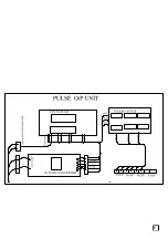
Страница 17: ...contact Pulse output b Pulse output for Second Minute Hour Day Pulse Pulse Output Duration 50 msec O P Connectors a Mounting connector BNC for all PFC contact output Pulse output Pulse contact duration 50 msec Supply Voltage 24 DC V supply from Redundant diode oring Environment a Temp 0 50 Deg C b RH 0 90 Non condensing Front Panel LED INDICATORS FOR Pulse Input output LED Indicator Back Panel ON ...

Страница 18: ...12 ...

Страница 19: ...S 232 Every minute Every Second O P Connectors RS 232 O P 9 PIN D connectors Supply Voltage 24V supply from Diode Oring Unit Environment a Temp 0 50 Deg C b RH 0 90 Non condensing Front Panel LED INDICATORS FOR RS 232 I P AND RS 232 OUTPUT Back Panel ON OFF Switch Fuse and Power Supply Terminals 1 RS 232 I P CONNECTOR 2 RS 232 O P CONNECTOR Panel Mounting To suit Standard 19 Rack System Dimension ...

Страница 20: ...14 ...

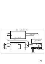
Страница 21: ... IRIG B AM O P 1 Khz O P Connectors IRIG B AM O P Through BNC connectors F Supply Voltage 24 DC V supply From Diode Oring Unit Environment a Temp 0 50 Deg C b RH 0 90 Non condensing Front Panel LED INDICATORS FOR IRIG B IN PUT AND IRIG B OUTPUT Back Panel ON OFF Switch Fuse Power Supply Terminals IRIG B I P BNC connector IRIG B OUTPUT BNC CONNECTOR Panel Mounting To suit Standard 19 Rack System Di...

Страница 22: ...16 ...

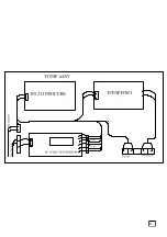
Страница 23: ... IP Output Every Second to PC Synchronizing O P Connectors RJ 45 Connectors Supply Voltage 24V supply from Diode Oring Unit Environment a Temp 0 50 Deg C b RH 0 90 Non condensing Front Panel Signal Input LED Signal Output LED and Power On LED Back Panel ON OFF Switch Fuse and Power Supply Terminals 1 RS 232 I P 9 Pin D Connector 2 TCP_IP Output RJ 45 Connector Panel Mounting To suit Standard 19 Ra...

Страница 24: ...18 ...

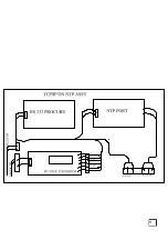
Страница 25: ...ector Outputs TCP_IP ON NTP Every Second O P Connectors RJ 45 Connector Supply Voltage 24V supply from Diode Oring Unit Environment a Temp 0 50 Deg C b RH 0 90 Non condensing Front Panel LED Indication for Signal Input LED and Signal Output LED Back Panel ON OFF Switch Fuse and Power Supply Terminals 1 RS 232 DATA I P 9 Pin D Connector 2 TCP IP ON NTP Output RJ 45 CONNECTOR Panel Mounting To suit ...

Страница 26: ...20 ...

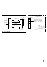
Страница 27: ...it Output Signal BCD Output Input Connector BNC Connector Output Connector 37 Pin D Connector Output From Instrument SECOND MINUTE HOUR IN BCD FORMAT TTL level Parallel BCD output for HH MM SS To drive up to 2 mts Length Modulation ratio Adjustable 2 1 to 4 1 2 V to 12V Level Front Panel LED indication Supply Voltage 24 V DC ...

Страница 28: ...22 ...

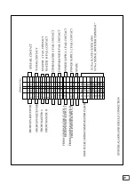
Страница 29: ...8 HOUR MSB 09 NO CONNECTION 10 MINUTE LSB 11 MINUTE LSB 12 MINUTE LSB 2013 MINUTE LSB 14 MINUTE MSB 15 MINUTE MSB 16 MINUTE MSB 17 MINUTE MSB 18 NO CONNECTION 19 SECOND LSB 20 SECOND LSB 21 SECOND LSB 22 SECOND LSB 23 SECOND MSB 24 SECOND MSB 25 SECOND MSB 26 SECOND MSB 27 NO CONNECTION 28 GROUND ve SUPPLY 29 GROUND ve SUPPLY 30 31 32 33 34 35 36 37 ...

Страница 30: ...y c 26 5 V DC to battery charging terminal d AC ON OFF DC ON OFF charger ON OFF switch e AC Fuse 4 Amp f DC fuse 2amp g Charger Fuse 4 Amp Mounting Panel Mounting 19 rack Dimension 484 W 325 D 3U H The battery is on float charge and is maintained at fully charged value at all times as long as the mains power is available In the event of power failure the change over to the battery is automatic and...

Страница 31: ...25 ...

Страница 32: ...26 ...

Страница 33: ...l Input 2 terminal Current rating 4 Amp Max Output Isolated 24V DC Supply to Modules Front Panel LED indicator Input 1on 2 on Out put on Back Panel 24VDC Input 1 terminal Input 2 terminal Input switch 1 2 Input fuse 1 2 Output Terminal Output Switch Output Fuse Mounting Suitable 19 rack mounting Dimension 3U H x 484 W x 325 D MM ...

Страница 34: ...28 ...

Страница 35: ... are connected to Master Clock by 3 core copper Conductor Multi Drop System Slave updation Every second Environments a Temperature 0 60 Deg C b RH 0 90 non condensing Mounting Wall Mounting Mounting Dimensions Width 700mm Ht 200mm Depth 110mm In its simplest form the Slave Clock is a binary counter with display The front end detects the leading edge of the pulse train sent by Comparator Unit and c...

Страница 36: ...30 ...

Страница 37: ...input and output Protection against cable short circuit Surge and lighting protection to safe guard the instrument terminals Model No T LD 300 T LR 300 Type Asynchronous Compatibility RS 232 C Max Baud rate 9600 bps constant non selectable Error rate Both input output are optically isolated Front Panel Signal indicator ON OFF Switch 9 pin D connector RS 232 input output connector Back Panel Fuse H...

Страница 38: ...32 ...

Страница 39: ...iode Oring Unit Signal Amplification Every second Environments a Temperature 0 50 Deg C b RH 0 90 non condensing Mounting 19 Rack Panel Mounting Dimension 2U H x 484 W x 325 D MM Note Slave Distribution amp work as a Signal Booster This having Provision of 4 Direction Connection Facility with Isolated Output If number of Slave Clock Connected with Slave Distribution Amplifier one will affect other...

Страница 40: ...34 ...

Страница 41: ...MULTI DROP SYSTEM Signal Amplification Every second Environments a Temperature 0 50 Deg C b RH 0 90 non condensing Mounting Wall Mounting Table Top Mounting Dimensions Width 125 mm Height 60 mm Depth 155mm PRINCIPLE Signal boosters are required only more then 10 Slave Clock connected or distance More then 300 Mts from Comparator unit Slave clock Signal Boosting is Required Signal Booster Connectio...

Страница 42: ...able 4 If The Antenna Cable more then 50 mtrs Between 50th Meter connect Inline Amplifier 5 Install the GPS receiver 6 Connect power supply ensuring proper polarity 7 Switching ON the 2X 240V AC 110 230V AC Power supply and conform POWER SUPPLY A B Input on LED are glow And Switch ON DC power supply conform 24V DC availability at terminal and 26 5V at BATTERY Volt all are ok Tern Switch ON MAINS O...

Страница 43: ...onditions and period of time from POWER ON to first fix are as follows Conditions and period of time from Power on to first fix are as follows Power on Accuracy availability of Initial Setting Validity TTFF Conditions L L Time Almanac Ephemeris Typical Warm Shaft Within 1 Deg Within 10 Min 1 Month 4 Hrs 20 Sec Cold Start Within 1 Deg Within 30 min 1 Month N A 45 Sec Autonomous Start N A N A N A N ...

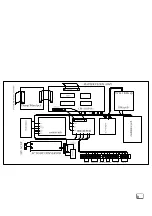
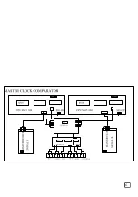
Страница 44: ...clocks generate necessary time signals and feed them to Redundant Comparator Units A B for further processing An alarm contact to indicate the non availability of synchronizing signals from the GPS unit is included in the clock system to provide visual indication of the failure status 04 Redundant Comparator Unit Redundant comparator This unit receives the time signal generated by Master Clock A a...

Страница 45: ...angements 2 Power Supply Units A B are provided They generate 24VDC isolated outputs and 26 5V DC to Charge the Battery The output of the power supply units A B are compared by a Diode Oring Power Supply Comparator to ensure availability of 24VDC output at all time 08 Slave Distribution amp and Signal Booster Slave Distribution amp provided for Four Direction Slave Clock Connection Diff Pulse slav...

Страница 46: ...e accuracy of GPS is 2 Drms two times distance root main square error Horizontal Accuracy 100 Mtrs Vertical Accuracy 146 Mtrs Time 100 nano seconds with respect to UTC time With selective availability these accuracies are degraded With respect to time the degradation is approximately 300 500 nano seconds 23 GPS RECEIVER WITH SATELLITE LOCK UNLOCK SERTEL provided satellite lock unlock indication Co...

Страница 47: ...thin 1 Seconds day c Provide tailor made 7 segment LED display of HRS MINTS and SECONDS in 24 Hours format d Keep the Master and Slave clocks in synchronization At any point of time Via Comparator Unit e Provide Time Related Signals as required by the customer f Provide outputs to synchronies other micro controller Process based digital clock system ...

Страница 48: ...izes its output frequency 3 Set Date and Times using THUMBWHEEL SWITCH DATE TIME TOGGLE SWITCH and ENTER PUSH BUTTON The procedure is given below 26 DATE SETTING PROCEDURE Insert the key in RESET LOCK and turn to ON Position Set DATE TIME TOGGLE S W to DATE Position Set the DATE through THUMNBWHEEL SWITCH marked DD MM and YY Example D D M M Y Y 09 MAR 2009 0 9 0 3 0 9 Enter the value by pressing t...

Страница 49: ... setting these turn the RESET LOCK to OFF position and remove the key This is to prevent inadvertent resetting of the clock when the enter push inadvertent resetting of the clock when the Enter push button s w is accidentally pressed Note Above procedure only discounting the GPS signal input to Master clock When GPS Receiver Connected With Master Clock By entering Master clock Thump Wheel Setting ...

Страница 50: ...lability of Satellite signal the built in oscillator of GPS receiver is used as time reference to update the GPS time system and give necessary time outputs to Master Clock 02 In case of failure of any one Master Clock the signal are automatically generated by the redundant clock 03 In case of non functioning of both Master Clocks the signals are fed directly from the GPS Receiver of the Redundant...

Страница 51: ...f days 11 Units of days 12 Tens of months 13 Units of months 14 Tens of years 15 Units of years 16 CR Carriage return 17 LF line feed 18 ETX End of text Format of Day of Week field B7 B6 B5 B4 B3 B2 B1 B0 Day 0 1 1 0 0 0 0 1 Monday 0 1 1 0 0 0 1 0 Tuesday 0 1 1 0 0 0 1 1 Wednesday 0 1 1 0 0 1 0 0 Thursday 0 1 1 0 0 1 0 1 Friday 0 1 1 0 0 1 1 0 Saturday 0 1 1 0 0 1 1 1 Sunday Note 1 The RS 232 C Ou...

Страница 52: ...ndard RS 232C as described for data terminal equipment DTE 9 pin D Connector M pin connections Pin Connections 1 NC 2 NC 3 RS 232 output 4 NC 5 Ground 6 NC 7 NC 8 NC 9 NC RS 232 output from SERTEL as follows Data transmission every second 6 0 HH MM SS DD MM YY CR LF STARTTING hour Second Month CARRIAGE CHARACTER RETURN minute Date Year LINE FEED RS 232 output from SERTEL as follows Level ASCII Dat...

Страница 53: ...ORMAT THL RS 232 OUTPUT RS 232 FORMAT BADURATE 2400 DATA BIT 7 PARITY EVEN STOP BIT 1 PIN Nos OUTPOT 1 NC 2 NC 3 RS 232 OUTPUT 4 NC 5 GROUND 6 NC 7 NC 8 NC 9 NC PROTOCAL XXX XX XX XX XXXX CRLF Julian hour minute second year day ...

Страница 54: ...Constant hexadecimal value FF Header 1 Constant hexadecimal value 01 State byte 1 See below Start of transmission 1 Constant hexadecimal value 02 Day of the week 1 Value in BCD 0 Monday to 07 Sunday Day in Month 1 Value in BCD 01 to 31 Month 1 Value in BCD 01 to 12 Year 1 Value in BCD 01 to 99 Hours 1 Value in BCD 00 to 23 Minutes 1 Value in BCD 00 to 59 Seconds 1 Value constant in BCD 02 End of t...

Страница 55: ...01 to 99 Month 1 Value in BCD 01 to 12 Day of the month 1 Value in BCD 01 to 31 Hours 1 Value in BCD 00 to 23 Minutes 1 Value in BCD 00 to 59 Seconds 1 Value constant in BCD 02 End of transmission 1 Constant hexadecimal value 03 Sync byte 1 Constant hexadecimal value 16 The time message comprises a state byte Value in hexadecimal Operation 00 Normal 01 Sync missing 02 Serious malfunction Above RS ...

Страница 56: ...pe cd then press enter 11 type cd c winnt system32 then press enter 12 Now verify that you are in c winnt system32 13 type mmc services msc in MS DOS Prompt or Run Dialog box 14 find timesync in services list and double click it 15 Make it is as automatic in start up type 16 goto Log on tab and enable Allow service to interact with desktop if you like to have a display on desktop 17 Apply the abov...

Страница 57: ...rt of TCP Internet protocol IP address to identify an individual computer IP network must have a unique IP address Sample IP address 192 168 1 254 PORT NUMBER The EAD serial channel port can be associated with a specific TCP Port number port number 3001 as a source port no is reserved for IFD internet Fax dialer configuration ertel Provided TCP IP output This will synchronies More Number of PC Thr...

Страница 58: ...n c winnt system32 14 type mmc services msc in MS DOS Prompt or Run Dialog box 15 find timesync_ip in services list and double click it 16 Make it is as automatic in start up type 17 goto Log on tab and enable Allow service to interact with desktop if you like to have a display on desktop 18 Apply the above settings and Start the service and see whether the display appears or not 19 Restart your P...

Страница 59: ...DDRESS windows ONLY NOTE1 SWITCH ON THE UNIT AND CONNECT THE ETHERNET CABLE WITH THE NTP UNIT NOTE2 YOU SHOULD CHANGE YOUR SYSTEM IP ADDRESS RELATED TO OUR DEFAULT IP ADDRESS 192 168 1 254 NOTE3 THEN ONLY YOU CAN ABLE TO CHANGE IP ADDRESS INSIDE NTP UNIT Click START at the bottom left corner of the desktop Click Run ...

Страница 60: ...to type telnet 192 168 1 254 and click ok It will show ts7200 login here you have to type admin then press enter button It will show password here you have to type ntp then press enter button Now you can see symbol ...

Страница 61: ...55 Now you should type the command cd etc sysconfig then press enter button Now you should type the command vi ifcfg eth0 then press enter button ...

Страница 62: ...sk details Here you can see IPADDR 192 168 1 254 at the second line Here you press down key to second line then press right key to move cursor right side up to end IPADDR 192 168 1 254_ Now you press x button till IPADDR _ then stop pressing ...

Страница 63: ... right key once this is for give 1 space between numbers and letters Now you type your IP address according to your requirement Note should not use any using IP address in your network After type your new IP address press Esc button two times Now you have to type wq colon wq press Enter ...

Страница 64: ...58 Now you can see symbol Now type reboot Now your ntp server IP addresses have been changed NOTE4 YOU SHOULD CHANGE YOUR SYSTEM DEFAULT IP ADDRESS ...

Страница 65: ...pe regedit then enter Click HKEY_LOCAL_MACHINE SYSTEM CurrentControlSet Services W32time Time Providers Ntpclient root key for the time service Right click specialpollinterval and click modify and delete the value 604800 and type 3C Click KEY_LOCAL_MACHINE SYSTEM CurrentControlSet Services W32time config root key for the time service ...

Страница 66: ...e value 54000 and type ffffffff Right click MaxPosPhaseCorrection and click modify and delete the value 54000 and type ffffffff Right click Update Interval and delete the value 00057e40 and type 3C Right click the time at the right bottom corner Select Adjust date time ...

Страница 67: ...u have to tick the option that Automatically synchronize with Internet Time Server Then you have to enter your new NTP server IP address inside the server box Now you click Apply then click Update Now option then click ok Now your system gets synchronized Close the date and time window ...

Страница 68: ...ties Now you have to select settings Here you have to enter your NTP server address and you have to select SNTP Here you have option for update intervals etc According to your wish you can enter your values and give ok Now it will show warning Here you click NO Now your pc time get synchronized STEPS TO SYNCHRONISE WITH Linux SYSTEMS In DOS mode type ntpdate u server address In graphics mode doubl...

Страница 69: ...ified output like 1 PPS 1PPM 1PPH 1PPD required user tap from required o p Through BNC Connector Pulse Signal Conditioner Rear Side Selector Switch or Thump wheel Provision Available please select the following procedure 37 SELECTOR SWITCH SELECTION For example a Selection of SECOND contact output Simply turn any one of selector knob to Sec location every Second one contact available At connector ...

Страница 70: ... 5 02 5 03 5 04 5 05 5 06 5 07 5 08 5 09 5 10 5 For example d Selection of SECOND in 1st Relay contact output Simply turn RL Thumbwheel in 01 and PC in 1 Every Second Contact Available at 1Marked Output Connector b Selection of MINUTE in 2 Relay contact output Simply turn RL Thumbwheel in 02 and PC in 2 Every Minute Contact Available at 2Marked Output Connector e Selection of Hour Relay Contact at...

Страница 71: ...cs film and for real time transmission in both automatic manual data reduction IRIG B from the SERTEL GPS MASTER CLOCK system is suitable for remote display driving magnetic tape recording and may other use IRIG B codes in the strip sense encode Universal Co ordinate Time UTC in 24 Hours format only not local time Nonetheless this instrument can encode UTC and IST time in 24 hours format The frame...

Страница 72: ...ed by two consecutive 8 0 ms bits Po and P1 The Leading edge of P1 is the on time reference point for the succeeding Time Code words Position identifiers Po and P1 through P9 8 ms duration occur every 10th bit and 10ms before the leading edge of each succeeding 10 pps on time bit ...

Страница 73: ...ansmitter on 77 5 kHz is a slow serial time code consisting of 60 bits transmitted at the rate of 1 bit s It takes 1 minute to deliver the full code This time code is handy for many types of applications and it is becoming widely used in Europe The coding is as follows Bit rate 1 bit sec Negative pulses beginning on the second open collector starts conducting Pulse duration 0 1 second value 0 Puls...

Страница 74: ...36 41 day of the month 42 44 day of the week Monday 1 45 49 month 50 57 year 58 combines with bits 36 57 for even parity 59 the pulse is missing minute identifier By menu the GPS unit may be programmed to stop delivering the DCF code when GPS synchronization is bad Minute Pulses Time Marks Minute pulses duration gives following indication Length Indication 1 second Minute mark when GPS synchroniza...

Страница 75: ...ith the DCF code operating on the internal quartz time base it allows to correct for the drift of the quartz time base The coding is as follows Slow code Time comparison between internal time and GPS time based on latest GPS Reading geo version Bits 1 to 12 milliseconds of GPS time at time T BCD coded 4 bits for every digit Bits 13 to 19 seconds of GPS time at time T Bits 21 to 41 time T time of t...

Страница 76: ...rt bit 7 data bits 1 parity bit even 1 stop bit Repetition rate 1 message every minute beginning exactly on the minute BCC XOR over all bytes from H to ETX even parity 2 HH MM SS MIS DD mm YY DOY d s CRLF Byte format 1 start bit 8 data bits 1 stop bit no parity Repetition rate 1 message every minute beginning exactly on the minutes Status byte normally 30H leap year 31H bad GPS synchronization 34H...

Страница 77: ...nute ending exactly on the minute K N for standard time winter S for daylight saving time summer Status byte S when good GPS synchronisation when bad GPS synchronisation LRC parity byte XOR over all bytes from K to s 5 YYmmDDHHMMSSd CRLF Byte format 1 start bit 7 data bits 1 extra bit 1 stop bit no parity Repetition rate 1 message every minute beginning on the minute ...

Страница 78: ...egoing warranty excludes routine maintenance and calibration The warranty does not apply to defects resulting from improper or inadequate maintenance unauthorized modification or misuse and operation of the product not in conformity with operation manual In case of any malfunction please deliver the equipment to our works and collect the same after repairs The equipment shall be dispatched to you ...

Страница 79: ......

Страница 80: ...01 ...

Страница 81: ...02 ...

Страница 82: ...03 ...

Страница 83: ...04 ...

Страница 84: ...05 ...

Страница 85: ...06 ...

Страница 86: ...07 ...

Страница 87: ...08 ...

Страница 88: ...09 ...

Страница 89: ...10 ...

Страница 90: ...11 ...

Страница 91: ...12 ...

Страница 92: ...13 ...

Страница 93: ...14 ...

Страница 94: ...15 ...

Страница 95: ...16 ...

Страница 96: ...17 ...

Страница 97: ...18 ...

Страница 98: ...19 ...

Страница 99: ...20 ...

Страница 100: ...21 ...

Страница 101: ...22 ...

Страница 102: ...23 ...

Страница 103: ...24 ...

Страница 104: ...25 ...

Страница 105: ...26 ...

Страница 106: ...27 ...

Страница 107: ...28 ...

Страница 108: ...29 ...

Страница 109: ......

Страница 110: ...A ...

Страница 111: ...B ...

Страница 112: ...C ...

Страница 113: ...D ...

Страница 114: ...E ...

Страница 115: ...F ...

Страница 116: ...G ...

Страница 117: ...H ...

Страница 118: ...I ...

Страница 119: ......

Страница 120: ...AA ...

Страница 121: ...BB ...

Страница 122: ...CC ...

Страница 123: ...DD ...

Страница 124: ...EE ...

Страница 125: ...FF ...

Страница 126: ...G GG ...

Страница 127: ......

Страница 128: ...a ...

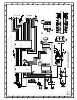
Страница 129: ...5 A6 A7 A8 G DIR B1 B2 B3 B4 B5 B6 B7 B8 U3 74LS245 2 3 4 5 6 7 8 9 19 1 18 17 16 15 14 13 12 11 A1 A2 A3 A4 A5 A6 A7 A8 G DIR B1 B2 B3 B4 B5 B6 B7 B8 U9 AT89C51 9 18 19 29 30 31 1 2 3 4 5 6 7 8 21 22 23 24 25 26 27 28 10 11 12 13 14 15 16 17 39 38 37 36 35 34 33 32 RST XTAL2 XTAL1 PSEN ALE PROG EA VPP P1 0 P1 1 P1 2 P1 3 P1 4 P1 5 P1 6 P1 7 P2 0 A8 P2 1 A9 P2 2 A10 P2 3 A11 P2 4 A12 P2 5 A13 P2 6...

Страница 130: ...HEADER 10X2 1 2 3 4 5 6 7 8 9 10 11 12 13 14 15 16 17 18 19 20 R3 R R2 R R5 10E 5W R4 R U20 74LS192 15 1 10 9 5 4 11 14 3 2 6 7 12 13 A B C D UP DN LOAD CLR QA QB QC QD CO BO U19 74LS192 15 1 10 9 5 4 11 14 3 2 6 7 12 13 A B C D UP DN LOAD CLR QA QB QC QD CO BO U17 74LS192 15 1 10 9 5 4 11 14 3 2 6 7 12 13 A B C D UP DN LOAD CLR QA QB QC QD CO BO U16 DIP14 1 2 3 4 5 6 7 8 9 10 11 12 13 14 1 2 3 4 ...

Страница 131: ... 74LS14 13 12 U22A 74LS14 1 2 U21A 74LS14 1 2 U21B 74LS14 3 4 C11 CNP D23 D 1 2 R30 R U22B 74LS14 3 4 R26 R R28 R Q17 SL100 3 2 1 Q19 TIP122 3 2 1 R24 R Q21 TIP122 3 2 1 U21E 74LS14 11 10 U22D 74LS14 9 8 C12 CNP D24 D 1 2 R31 R U22E 74LS14 11 10 U22C 74LS14 5 6 U22F 74LS14 13 12 C9 CNP C10 10MF Q5 SL100 3 2 1 R10 R Q9 BC548 3 2 1 R15 R R18 R R11 R R13 R Q2 SL100 3 2 1 Q6 TIP122 3 2 1 R7 R Q10 TIP1...

Страница 132: ... MISO PB7 SCK PD0 RXD PD1 TXD PD2 INTO PD3 INT1 PD4 TO PD5 T1 PD6 ICP C20 CNP C19 CNP C18 CNP R34 R R32 R U25 DIP14 1 2 3 4 5 6 7 8 9 10 11 12 13 14 1 2 3 4 5 6 7 8 9 10 11 12 13 VCC U26 74LS244 2 4 6 8 11 13 15 17 1 19 18 16 14 12 9 7 5 3 1A1 1A2 1A3 1A4 2A1 2A2 2A3 2A4 1G 2G 1Y1 1Y2 1Y3 1Y4 2Y1 2Y2 2Y3 2Y4 R35 R C13 CNP D25 D 1 2 R33 R C16 CNP C14 CNP C15 CNP R36 R R37 R R39 R JP9 HEADER 8 1 2 3...

Отзывы: