SOL-96.110.051 / 260422
TOPAZ Total Hardness
Safety Instructions
5
Warning signs
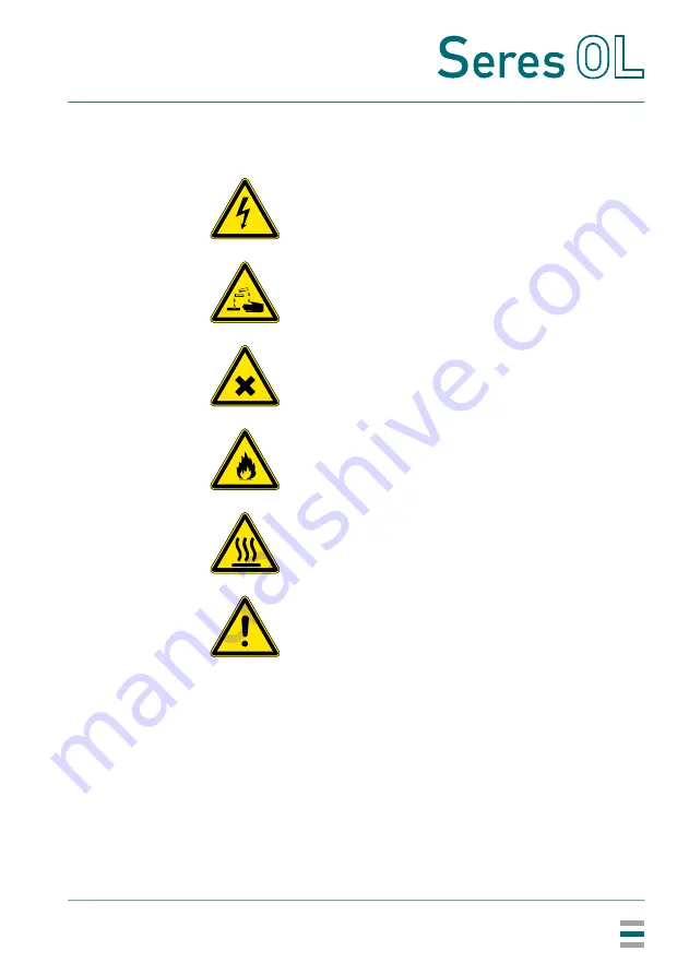
The warning signs in this manual have the following meaning:
Electrical shock hazard
Corrosive
Harmful to health
Flammable
Hot surface
General warning
Страница 1: ...TOPAZ Total Hardness Operator s Manual TOPAZ Total Hardness SOL 96 110 051 260422...
Страница 2: ...staff of technical specialists around the world For any technical question contact your nearest Seres OL representa tive or the manufacturer Seres OL SAS ZA de la Sipi re 219 Avenue de Provence FR 13...
Страница 3: ...3 4 1 Connections on I O Board 15 3 4 2 Cable thicknesses 19 3 4 3 AC power 20 3 4 4 Jbus via RS485 21 3 4 5 Jbus via TCP IP Option 22 4 Startup 23 4 1 Installing the Reagent Bottles 23 4 2 Starting S...
Страница 4: ...ardness 2 6 6 2 Standard Calibration 41 6 7 Longer Stop of Operation 41 7 Configuration of the Analyzer 42 8 Troubleshooting 46 8 1 What To Do If 46 8 2 List of Errors and Alarms 50 8 3 Saving Diagnos...
Страница 5: ...afety instructions are given throughout this manual at the respective locations where observation is most important Strictly follow all safety instructions in this publication Target audience Operator...
Страница 6: ...low the prevention instructions carefully WARNING Severe injuries or damage to the equipment can occur if such warnings are ignored Follow the prevention instructions carefully CAUTION Damage to the e...
Страница 7: ...260422 TOPAZ Total Hardness Safety Instructions 5 Warning signs The warning signs in this manual have the following meaning Electrical shock hazard Corrosive Harmful to health Flammable Hot surface G...
Страница 8: ...accordance with the local regula tions of the respective country WARNING Electrical shock hazard If proper operation is no longer possible the instrument must be disconnected from all power lines and...
Страница 9: ...lyzer and check it for visible damage If the analyzer shows any visible damage do not connect it to power and contact customer service immediately 1 4 International Symbols Used The symbols found on t...
Страница 10: ...ess HR 10 100 ppm CaCO3 15 300 ppm CaCO3 30 600 ppm CaCO3 Available with one two four or six measuring channels common measuring range Signal outputs Two signal outputs per measuring channel Current l...
Страница 11: ...ammable liquids or gases Protect it from bad weather humidity corrosive substances and dust Process connections Sample inlet Sample outlet Sample outlet waste 1 4 BSP F soft tubing D INT 9 single chan...
Страница 12: ...nge Limit of detection Repeatability Accuracy LR 5 50 ppm CaCO3 5 ppm 5 FS 5 FS Instrument variant Range selection Limit of detection Repeatability Accuracy HR 10 100 ppm CaCO3 or 15 300 ppm CaCO3 or...
Страница 13: ...422 TOPAZ Total Hardness Product Description 11 Wall cabinet Material Screws Weight Protection degree Stainless steel SS316L 4x M6 6x M6 with reagent shelf 35 kg IP55 Reagent shelf made of SS316L avai...
Страница 14: ...Description 12 2 2 Instrument Overview A B C D E F G H I J K Power switch Touchscreen Cable glands Peristaltic pumps Photometer Air cleaning inlet Pressure reducing device Calibration vessel Sample i...
Страница 15: ...cifications p 9 3 2 Mounting the Wall Cabinet Mounting requirements Mount the instrument in vertical position The display should be at eye level to simplify operation and maintenance For dimensions se...
Страница 16: ...te the instrument from a power outlet which has a protec tive earth connection Overview of electrical connections 1 In multi channel instruments there is an I O board for each measuring channel The I...
Страница 17: ...used to control internal components of the analyzer Do not connect anything else to these contacts Analog signal output OUT_ANA2 is reserved for customized versions of the analyzer that provide a seco...
Страница 18: ...Leave pins 1 and 4 unconnected Analog signal outputs 4 20 mA Name Available on Description IN_DIG1 all measuring channels Activates or deactivates the measuring channel Open contact Measuring channel...
Страница 19: ...the Analyzer p 42 Name Available on Description OUT_DIG2 all measuring channels Sample flow alarm OUT_DIG3 all measuring channels Threshold 1 OUT_DIG4 all measuring channels Threshold 2 OUT_DIG5 all...
Страница 20: ...e configured as normally open or normally closed by setting the corresponding jumpers on the I O board The default setting is normally open jumper in the right position A Location of jumpers on I O bo...
Страница 21: ...l Hardness Installation 19 3 4 2 Cable thicknesses In order to comply with IP55 use the following cable thicknesses Note Seal cable glands that are not in use A B Outer diameter of cable 7 5 13 mm Out...
Страница 22: ...2 TOPAZ Total Hardness Installation 20 3 4 3 AC power Ferrite Wrap the mains cable two times around the supplied ferrite A B C Protective earth PE terminal 3 Neutral conductor terminal 2 Phase conduct...
Страница 23: ...SOL 96 110 051 260422 TOPAZ Total Hardness Installation 21 3 4 4 Jbus via RS485 Terminals Terminal 1 data B terminal 2 data A A RS485 interface A...
Страница 24: ...analyzer The connection is made via the Ethernet port located on the right side of the analyzer exterior Mount the supplied connector onto the Ethernet cable and connect it to the port Addressing mode...
Страница 25: ...e This will prevent the tube ends from lying flat on the bottom of the bot tles 2 Check that there are two holes in the lid of each reagent bottle one hole to feed the reagent tube through and one sma...
Страница 26: ...TOPAZ Total Hardness Startup 24 4 2 Starting Sample Flow Open the sample tap C so that a part of the sample overflows into the pressure reduction device A A B C Pressure reduction device Inner tube S...
Страница 27: ...mps are automatically readjusted and the panel PC starts 2 Stop the measuring cycle by pressing the button and entering the password 0712 3 Open the TOOLS tab and press the Electrical test button Chec...
Страница 28: ...n next to P1 HNB indicator 8 Let the pump run until the fluid has reached the photometer and there is no more air in the tube This takes approximately 2 5 minutes The pump stops automatically 9 Repeat...
Страница 29: ...he ACTUATOR tab 11 Set SV Emptying to ON and SV Filling to OFF and wait until the instrument is empty 12 Remove the lid from the photometer 13 Check that the stirrer bar is turning 14 Reinstall the li...
Страница 30: ...s necessary 2 Calibrate the analyzer if required For detailed descriptions see Manual Measurement and Calibration p 39 4 6 Programming Program the following parameters if applicable Concentration valu...
Страница 31: ...ined access levels User access Allows viewing data in the main window Access with extended permissions Allows stopping the measurement changing settings and performing maintenance tasks The password f...
Страница 32: ...t manual measurement C Measured value D Trend E Measuring cycle information Stream that is being measured Number and description of step in measurement cycle Total number of steps to be completed F Da...
Страница 33: ...ion is needed If necessary calibrate the instrument Every 3 months Replace all peristaltic pump tubes After replacement of peristaltic pump tubes perform a manual measurement with a standard solution...
Страница 34: ...he photometer flush the reagent tubes one after the other not simultaneously Proceed as follows 1 Remove all reagent tubes from their bottles and place them in a beaker filled with deionized water 2 O...
Страница 35: ...he ACTUATOR tab and set SV Filling to ON 7 Wait until the photometer has been filled with fresh water Then set SV Filling to OFF ON ON ON ON OFF OFF OFF OFF Stirrer SV Emptying Heating SV Filling ACTU...
Страница 36: ...sumed Hydroxynaphtol blue 3 liters per month Buffer D2 pH 10 4 5 liters per month H2SO4 2N 3 liters per month The concentration of the EDTA reagent varies depending on the selected measuring range The...
Страница 37: ...gent type 11 HNB PTFE 1 6 3 2 12 HNB PTFE 1 6 3 2 21 D2 buffer PTFE 1 6 3 2 22 D2 buffer PTFE 1 6 3 2 91 H2SO4 2N PTFE 1 6 3 2 92 H2SO4 2N PTFE 1 6 3 2 31 EDTA N x PTFE 1 6 3 2 32 EDTA N x PTFE 1 6 3...
Страница 38: ...g device A SVB NC Silicone 5 8 Calibration vessel B SVB NO Silicone 5 8 SVB C Sample inlet right of photometer D Silicone 5 8 Water fault sensor U1 Silicone 2 5 Photometer sample outlet left SVA NC Ty...
Страница 39: ...s Wear appropriate protective equipment gloves glasses protective clothing 1 Flush the reagent tubes with deionized water as described in Stop of Operation for Maintenance p 32 2 Turn the power switch...
Страница 40: ...ll the tube around the rotor while turning it 6 Connect the other tube end to the left side fitting 7 Install the front cover on the pump 8 Insert the reagent tubes all the way to the bottom of the co...
Страница 41: ...calibration contact customer service for details Entering the maintenance menu 1 To stop the current measuring cycle press the button on the main screen and enter the password 0712 In the next dialog...
Страница 42: ...l A with the standard 3 Wait until the calibration vessel is empty and the message Add standard appears again 4 Repeat steps 2 and 3 until the measurement starts automatically 5 When the measurement i...
Страница 43: ...the new calculated calibration coefficient and the concentration measurement readings before and after calibration Confirm by pressing the button 6 7 Longer Stop of Operation If the instrument is goin...
Страница 44: ...so by Seres OL customer service pressure setting Setpoint of the water fault sensor Adjust this value only if instructed to do so by Seres OL customer service Gain setpoint Setpoint of the electronic...
Страница 45: ...analyzer is designed for continuous operation a maximum duration of 15 minutes is recommended for pauses 1 Press the Add button and select one of the following options Pause Stream 1 Streams 2 3 4 5 o...
Страница 46: ...DIG3 and OUT_DIG4 are high or low thresholds The combinations high high low high and low low are possible The threshold values can be set in the parameter menu see 45 DATE TIME tab Set time and date A...
Страница 47: ...shold value is made in the THRESHOLD tab of the OPTIONS menu Threshold 2 Threshold value for relay OUT_DIG4 The definition as high or low threshold value is made in the THRESHOLD tab of the OPTIONS me...
Страница 48: ...rror message Water default although there is sample flow Possible cause Corrective action No power on the socket Check mains power supply Power supply defective Check output voltage of the internal 24...
Страница 49: ...Emptying solenoid valve SVA does not switch Check that the solenoid valve is plugged in correctly If necessary change the membrane Possible cause Corrective action Pump does not work properly Check t...
Страница 50: ...has passed or if the reagents have been stored incorrectly If necessary replace the reagents Check that the reagents are of Analysis Use quality ask supplier Tubes connected to the wrong reagent conta...
Страница 51: ...m is working correctly if present If no filter system is installed it might be necessary to install one Water does not drain Check that the drain is pressure free and not blocked Check condition of em...
Страница 52: ...in If the error persists contact customer support 5 Error reading cycle zero configuration Reset analyzer configuration to factory defaults by pressing the Recover button in the tab 6 Error writing cy...
Страница 53: ...Live optical measure value in the DIAGNOSTIC tab With a functioning measuring card the value changes continuously If the value does not change restart the analyzer and check again If the error persis...
Страница 54: ...the INPUT tab and test the digital inputs If the error persists contact customer support 20 Error reading on IO card Check if all I O boards work properly Navigate to TOOLS Electrical test Open the R...
Страница 55: ...r button in the tab 25 Error reading on JBUS slave card Check request compliance with JBUS protocol 26 Error treatment on JBUS slave card Check request compliance with JBUS protocol 27 Error reading m...
Страница 56: ...ary replace the membrane Check sample tubes 33 Optical setting Default Info setting not received Observe the Live optical measure value in the DIAGNOSTIC tab With a functioning measuring card the valu...
Страница 57: ...eps Check that the reagents are well injected into the photometer Check that the stirrer turns 41 Calibration coefficient outside tolerances new coefficient differs from the previous one by more than...
Страница 58: ...al fibers are well connected to their holder on the door 46 Incorrect projector power Contact customer service 47 Threshold 1 exceeded Check process Check programmed value for threshold 1 48 Threshold...
Страница 59: ...t G 255 analyzer cannot adjust the optical gain Check that the optical fibers are well connected to their holder on the door Check that the photometer is not dirty Check that the analyzer is supplied...
Страница 60: ...rt the USB stick into the USB port A on the back of the panel PC 3 Open the TOOLS tab and press the Log files copy button Enter the password 0712 if necessary 4 On the next screen press OK to start da...
Страница 61: ...TOPAZ Total Hardness Notes SOL 96 110 051 260422 59 9 Notes...
Страница 62: ...O i l G a s Seres OL SAS FR 13730 Saint Victoret www seres ol com info seres ol com Seres OL Products Analytical Instruments for Seres OL is represented worldwide by subsidiary companies and distribu...