background image

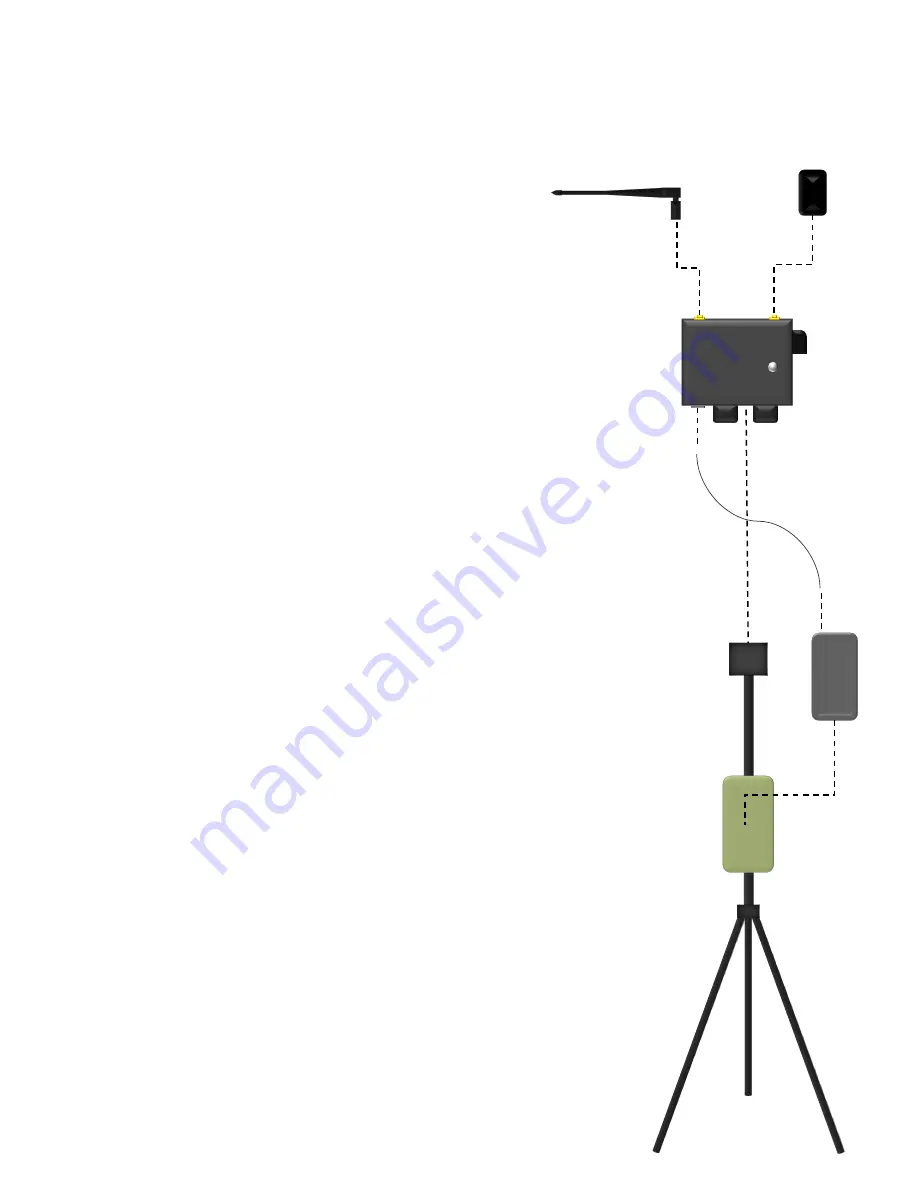
Setup and Assembly

2

1.

Remove the tripod, fully extend, and lock the 
legs.

2.

Mount the main unit to the tripod.

3.

Attach the GPS antenna to the connector on 
the top of the main unit labeled GPS. Turn
until finger tight.

4.

Attach the 900MHz antenna to the connector 
on the top of the main unit label 900 MHz.
Turn until finger tight.  For most applications, 
point the tip of the antenna straight up 
towards the sky.

5.

Place the battery into the bag attached to the 
tripod.

6.

Plug one end of the power cable into the 
battery and the other into the power 
receptacle on the main unit. 

7.

Ensure the Base Station has an 
unobstructed view of the sky.

Содержание RTK

Страница 1: ...RTK Base Station User Guide Revision Date 2019 08 29 ...

Страница 2: ...Table of Contents System description 1 Setup and assembly 2 Operation 3 Manual entry of base coordinates 4 Use with PHX 5 ...

Страница 3: ...lation GNSS module a 900 MHz telemetry link and a 2 port Ethernet switch for real time correction message forwarding 1 1 Main Unit 2 Dual frequency GPS Antenna 3 900 MHz Antenna 4 Status LED 5 Ethernet jack 2 6 Power Receptacle 7 Power Cable 8 Battery and Bag 9 Tripod 1 3 2 8 9 7 4 5 6 ...

Страница 4: ...4 Attach the 900MHz antenna to the connector on the top of the main unit label 900 MHz Turn until finger tight For most applications point the tip of the antenna straight up towards the sky 5 Place the battery into the bag attached to the tripod 6 Plug one end of the power cable into the battery and the other into the power receptacle on the main unit 7 Ensure the Base Station has an unobstructed ...

Страница 5: ...The status LED will indicate auto survey progress using the following light codes Red and white blinking Indicates the base station is acquiring a GPS fix This may take several minutes Blue and white blinking Indicates the base station is gathering location samples to determine its position This process takes approximately 2 minutes to complete Green and white blinking Indicates the auto survey ha...

Страница 6: ... For use with a Sentera PHX skip step 1 2 Connect an Ethernet cable between one of the Ethernet jacks on the main unit and your computer 3 In a web browser navigate to 192 168 143 31 A base station web page should appear 4 Enter the Latitude Longitude and Altitude of the GPS antenna into the appropriate boxes on the web page 5 Press the Write Settings button 6 The status LED on the front panel wil...

Страница 7: ... Setup Using standard Ethernet cables 1 Connect your PHX CommsBox to an Ethernet jack on the base station Power on both the CommsBox and RTK base station 2 Connect your laptop to the other Ethernet jack on the base station 5 ...

Отзывы: