www.sentera.eu
MIW-RSTHX-2-EN-000 - 06 / 11 / 2019
7 - 9
Fig. 3
Mounting position
Correct
Incorrect
Position at min. 1,5 m
from the floor
4.
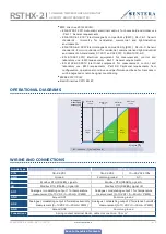
Do the wiring according to the wiring diagram (see
Fig. 4
).
Fig. 4
Wiring and connections
Analogue / modulating
output 1 - T
Analogue / modulating output
2 - rH
Supply voltage
RSTHF-2:
18—34 VDC
RSTHG-2:
18—34 VDC /
15—24 VAC ±10 %
Modbus
RTU
A
/B
5.
Put back the cover snap it in.
6.
Switch on the mains supply.
7.
Customise the factory settings to the desired ones via the 3SModbus software
or Sensistant (if necessary). For the default factory setting refer to the product
Modbus register map
.
For the complete Modbus register data, refer to the product Modbus Register
Map, which is a separate document attached to the article code on the website
and contains the registers list. Products with earlier firmware versions may not be
compatible with this list.
NOTE
5.
Optional settings
To assure correct communication, the NBT needs to be activated in only two devices
on the Modbus RTU network. If necessary, enable the NBT resistor via 3SModbus or
Sensistant (
Holding register 9
).
Example 1
Example 2
RX
ТX
NBT
NBT
NBT
Slave 2
Master
Slave n
Slave 1
Slave 2
Slave 1
RX
ТX
NBT
NBT
Master
Slave n
NOTE
On a Modbus RTU network, two bus terminators (NBTs) need to be activated.
RSTHX-2
COMBINED TEMPERATURE AND RELATIVE
HUMIDITY ROOM TRANSMITTER

