background image


MA-WIRELESS-T24-HS_EN

Page 6 on 21 

Rev: 

09/05/2011


2.2.2.


Home 


We now have successful communications with the base station so we can now pair with our device or we can 
select the Spectrum Analyser mode or Data Provider Monitor mode. 

 
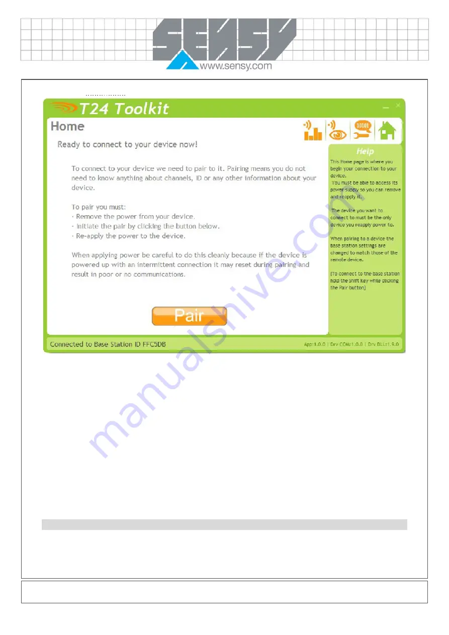
To connect to our device we will pair. This is achieved by power cycling the device. Pairing removes the need 

to know the radio settings of the device you are connecting to and also ensures that it is in a suitable state for 
configuration. 


Pairing Procedure 


Remove power from the acquisition module. 


Click the Pair button on the toolkit. 


You now have 10 seconds to re-apply power to the handheld module. 


If you connect successfully the toolkit will change to the Information page. 
If the pairing fails try again. 


NOTE: Pairing with the toolkit will not change the radio configuration settings of the connected device. 


Содержание WIRELESS-T24-HS

Страница 1: ...lyser 7 2 2 4 Data Provider Monitor 8 2 2 5 Information 9 2 2 6 Zero Settings 10 2 2 7 Display Format 11 2 2 8 Display Format Advanced Settings 12 2 2 9 Channel and Encryption 13 2 2 10 Save and Restore 14 2 2 11 Advanced Settings 15 3 INSTALLATION 16 3 1 Overview 16 3 2 Antenna Orientation 17 3 3 Battery 17 4 SPECIFICATIONS 17 4 1 General Radio 17 4 2 WIRELESS T24 HS 18 5 APPROVALS 18 5 1 CE 18 5...

Страница 2: ...rned off until the acquisition module is ready To turn off just hold down the power key until the display shows BUSY then release it 1 1 1 2 Acquisition Module See the acquisition module manual 1 1 2 Pairing We will use automatic pairing to prove the connectivity and operation Pairing sets the communications configuration parameters to allow the two devices to communicate We do not need a PC or la...

Страница 3: ...wing Gross weight NET The display is showing Net weight SIG LOW The radio signal from the acquisition module is low The device is still functioning but the limit of the range may be near Communications may start to deteriorate when this indicator is visible Until is displayed the communications is still OK and the display can be relied on for accuracy Note Even with a degraded signal the display v...

Страница 4: ... Installation 2 1 1 T24 Toolkit To configure the devices we must use the T24 Toolkit software application This can be downloaded from our web site or may be shipped with your products Install this on a PC or laptop Run setup exe and follow the prompts to install the software 2 1 2 T24 BSu Base Station If you have a USB version of the base station T24 BSu then you just need to plug this into a USB ...

Страница 5: ...shown when a T24 SA strain gauge acquisition module is connected 2 2 1 Setup Base Station Communications Select USB as the interface and select 1 as the Base Station Address In the toolkit all items that can be changed by the user are coloured orange To change a value just click on the relevant orange item You will then be presented with a new dialog window allowing you to change the value This ma...

Страница 6: ...ng removes the need to know the radio settings of the device you are connecting to and also ensures that it is in a suitable state for configuration Pairing Procedure Remove power from the acquisition module Click the Pair button on the toolkit You now have 10 seconds to re apply power to the handheld module If you connect successfully the toolkit will change to the Information page If the pairing...

Страница 7: ...poor communications issues This page shows the radio signal levels detected across all the channels available to the T24 series of devices Using this tool may help in detecting noisy areas and allow you to decide on which channels you may want to use The above charts show the traffic from a Wi Fi network and it can be seen to be operating over channels 6 to 9 and it would be best though not essent...

Страница 8: ...kets which may be useful for checking that a device is operational NOTE When the toolkit connects to a device to enable configuration it will usually inhibit the transmission of Data Provider packets The Start Logging button will ask for a filename and proceed to log the received data to a CSV file in the following format The View Last Log button will launch the application associated with CSV fil...

Страница 9: ...2 2 5 Information Once successfully paired to a device this page is displayed This page shows you information about the connected device Items you can change Name You can enter a short description which may help you recognise this device in the future ...

Страница 10: ...es that will be placed on the platform later The minimum weight of a box is 5 Kg so you could set the Power On Auto Zero to 2 Kg When you turn on the handheld if the weight on the platform is between 2 and 2Kg then the handheld will tare this weight off and so read zero Zero Indication Band Using this setting you can mask tiny changes in input after you press the Tare button Entering zero will dis...

Страница 11: ...ze of changes to the display Example If you enter the format as 000 0005 the display will only change in steps of 0 0005 which can be used to mask noisy digits at high resolutions Leading Zero Suppression This can be turned on or off and will suppress leading zeroes when on Example If the display reads 000 123 with leading zero suppression turned off it will display 0 123 when turned on Overload L...

Страница 12: ...isplay Update Rate Enter the interval in milliseconds between display updates The default is 300 milliseconds i e 3 updates per second Custom Display Scaling This can be used to change the displayed value to a different unit or to otherwise scale it You simply enter the original and required values at a low and high point Example If a T24 SA was supplying data in Kgs and you wanted to show tonnes ...

Страница 13: ... the acquisition module will be configured to match the handheld NOTE Early T24 modules do not yet utilise the encryption keys so these should be left at all zeros Items you can change Channel Select a channel between 1 and 16 The default is channel 1 You can use the Spectrum Analyser mode to determine a good clean channel to use NOTE Channel 16 is used to negotiate pairing so avoid this channel i...

Страница 14: ...ve the configuration file to All configuration information including calibration data will be saved to the file The file extension is tcf Restore Click this button to open a file dialog window to allow you to select a filename and location of a previously saved file to load into the connected device All configuration information including calibration data will be overwritten The file extension is ...

Страница 15: ...e default is On Auto Off Delay Here you can specify the delay in minutes after which the handheld will automatically turn off after no button is pressed Enter zero to disable this function The default is 5 minutes The On Off key can be used to reset this by giving a quick press This may be more suitable than using the Tare key Keep Awake Interval While the handheld is retrieving data from the acqu...

Страница 16: ...erials for product enclosures preference should be given to fibreglass light coloured ABS or Polypropylene at the wavelength of 2 4GHz radio other materials will adversely affect the signal by attenuation refraction or change in polarisation If the application demands that the radio is fitted inside a metal enclosure then ensure that the specified clearances are maintained around the antenna and d...

Страница 17: ...her voltage requirements of this device NiMh and NiCad batteries are not recommended 4 SPECIFICATIONS 4 1 General Radio Min Typical Max Units License License Exempt Modulation method MS QPSK Radio type Transceiver 2 way Data rate 250 K bits sec Radio Frequency 2 4000 2 4835 GHz Power 1 mw Range RAD24i Integrated antenna 120 400 Metres feet Range RAD24e External antenna 200 650 Metres feet Channels...

Страница 18: ...The Radio Equipment and Telecommunications Terminal Equipment R TTE Directive 1999 5 EC European Community Switzerland Norway Iceland and Liechtenstein English This equipment is in compliance with the essential requirements and other relevant provisions of Directive 1999 5 EC Deutsch Dieses Gerät entspricht den grundlegenden Anforderungen und den weiteren entsprecheneden Vorgaben der Richtlinie 19...

Страница 19: ...n och andra relevanta bestämmelser i Direktiv 1999 5 EC This equipment is in compliance with the essential requirements and other relevant provisions of Directive 1999 5 EC 5 2 FCC Family RAD24 Models i and e for internal and external antenna variants For antenna T24 ANTA and T24 ANTB FCC ID VHARAD24 This device complies with Part 15c of the FCC Rules Operation is subject to the following two cond...

Страница 20: ...ust ensure that the text on the external label provided with this device is placed on the outside of the final product 2 The acquisition modules with external antennas may be used only with Approved Antennas that have been tested by SENSY 6 2 IC Labelling requirements for Industry Canada are similar to those of the FCC A clearly visible label on the outside of the final product enclosure must disp...

Страница 21: ...aterial and workmanship for a period of 1 one year from the date of dispatch If the SENSY product you purchase appears to have a defect in material or workmanship or fails during normal use within the period please contact your Distributor who will assist you in resolving the problem If it is necessary to return the product to SENSY please include a note stating name company address phone number a...

Отзывы: