Network Wiring (MX-5000 Series)
MPS-4100 product guide • • • 2 - 29
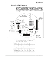
3. Connect the Slave Receiver inputs for audio, alarm, self-test and tamper to
TB3. The inputs for alarm and tamper must be NC 3 k
Ω
supervision. The
return wires for alarm, tamper, audio, and self-test may be tied to any
Common terminal on TB3. Connect the audio pair shield to any Common
terminal on TB3.
4. Set the Receiver modulation frequency to match the Transmitter modulation
frequency via JP1 and JP2.
5. Set the address for the transponder. Refer to the MX-5000 manual for network
device addressing. The transponder inserts upside down with the
DIP-switches positioned at the top.
6. Configure the operating parameters via S1 and S2. See Table 2-4.
Slave Receiver
The Slave Receiver is wired according to the Relay Output method. Relay outputs
for alarm and tamper must be set for NC, 3 k
Ω
supervised via jumpers JP3, JP4,
JP5, and JP6 (see Figure 2-10). The 3 k
Ω
EOLR for the tamper circuit should be set
at the Slave Transmitter. The return wires for alarm, tamper, audio and self-test
may be commoned together.
Figure 2-23 MPS-4100 Host Receiver connections
TB1
TB2
TB3
S2
+ - + - + -
AUD PWR
DATA/
TEST
TMP ALM
XMTTR
CONNECT
TMPR
-
+PWR
COM
ALM 2
TMPR
TEST 2
COM
AUD 2
CH6
CH5
CH4
CH3
CH2
CH1
XPNDR
CONNECT
Audio O/P
to MX-5000
Tamper O/P
from Transmitter
tape shield
JP1
JP2
S1
1 2 3 4 5 6
ON
OFF
1 2 3 4 5 6
ON
OFF
12 to 24 VDC O/P to
Transmitter and Slave Receiver
12 to 24 VDC I/P
from power supply
MPS-4100
Microwave Receiver
Alarm I/P from
Slave Receiver
Tamper I/P from
Slave Receiver
Audio I/P from
Slave Receiver
audio shield
to common
MX-5000 network
transponder card
installed on PI
XPNDR CONN
P1
Data communication
bus (I/O to MX-5000)
tape shield
connect return
wires to either
common terminal
Test O/P to
Slave Receiver
Содержание MPS-4100
Страница 1: ...Product MPS 4100 Microwave Protection System Guide E6DA0102 003 Rev C Third Edition April 27 2009 ...
Страница 6: ......
Страница 70: ......


