MPS-4100 product guide • • • 2 - 1
2
Installation
Installation planning
Refer to Do’s and Don’ts a planning primer, in Appendix a for
information about site planning and design.
Begin with a site survey to ensure that the area being protected meets the
MPS-4100 installation requirements. Next, determine the locations of the
Transmitter and Receiver pairs. Install the mounting posts, conduit and junction
boxes in the selected locations. The MPS-4100 can then be mounted, wired and
configured.
There are two methods of wiring and configuring the MPS-4100 depending on the
application. The Wiring and Configuration section of this chapter is divided into
Relay Output wiring and Network wiring.
Positioning the MPS-4100
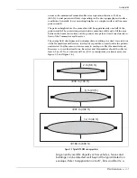
First, you must establish the length of each microwave zone. The maximum
separation distance between the Receiver and Transmitter is 183 m (600 ft.)
However, for high security applications, the recommended maximum separation
distance is 100 m (328 ft.). The maximum width of the zone is determined by the
amount of open space to the left and right of the center-line between the
Transmitter and Receiver. The area to be protected must be free of obstructions
and moving objects such as trees, shrubs, bushes, utility boxes and other
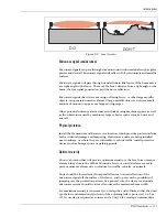
structures. Figure 2-1 illustrates the relationship between zone length and width.
Do’s and Don’ts a planning primer in Appendix a includes a formula for
calculating the approximate beam width based on the zone length.
Generally, there must be a clear open space that exceeds one
half the pattern width on each side (i.e., the minimum required
clear area is equal to two times the microwave beam width).
Large nearby metallic objects such as vehicles, fences and
buildings can be detected well beyond the typical detection
Содержание MPS-4100
Страница 1: ...Product MPS 4100 Microwave Protection System Guide E6DA0102 003 Rev C Third Edition April 27 2009 ...
Страница 6: ......
Страница 70: ......


