INSTRUCTIONS MANUAL
Installation Recommendations
Intelligent Valve Monitor
PSH5-M32-ASI3.2S-Ex
Страница 1: ...INSTRUCTIONS MANUAL Installation Recommendations Intelligent Valve Monitor PSH5 M32 ASI3 2S Ex ...
Страница 2: ...on the actuator for greater reliability because the sensors are polarized ie the sensor 1 detects only the magnet with north pole and sensor 2 only detects the magnet with the south pole thus avoiding inverted detection System Functioning The electronic sensor detects the magnetic actuator installed on the local signaller and sends a signal to the network with the valve positioning Trigger with Op...
Страница 3: ...river is provided with a M6x40 screw with the actuator site and M6x30 visual signaling to the driver without local visual cue and shaft must have a hole deeper than 20mm Shaft Height M32 line sensors are supplied with 5 mm or 10 mm spacers thus enabling the use of actuators on shafts of different heights The shaft height should be adequate so that the driver does not scrape the bottom of the actua...
Страница 4: ...e screwdriver loosen the three screws from the terminal box to gain access to the connectors 5 Disengage the cover holding the connectors to the terminal box 6 Remove the locking nut and seal rubber from the cable gland nº 1 7 Prepare the cable by baring its outer cover by maximum 40 mm 8 We also recommend the use of pre insulated terminals at the ends of the wires to avoid problems of poor contac...
Страница 5: ...crewdriver and wide slot 11 With all prepared cables insert the nut of the cable gland and the rubber seal on the cables that will be used 12 Insert the cables through the cable gland holes and mount them but do not overtighten 13 Fasten the wires to the terminals observing the connection diagram 14 Push the connector into the junction box help pulling cables 15 Put the connector cover if necessar...
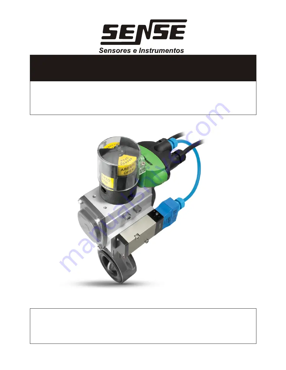
Страница 6: ...rs with or without local visual indication 01 Place the magnet on the actuator on the top face marked inside 02 Place the magnet on the bottom of the actuator face checked out 03 Mount the metal cover over the magnet in your accommodation 04 Fold tabs for fixing the metal cover 02 01 03 03 04 Dobra ...
Страница 7: ...r type NO NC Adjust the local indicator according your application and then tighten the fixing screw 5 Now place the monitor on the actuator 6 Place the acrylic on the trigger then the two M5 screws and tighten with a proper key but do not overtightening to avoid damaging the acrylic 1 Mount the local indicator on the actuator shaft inserting the spacers as needed according to the height axis 2 Th...
Страница 8: ...s programmed to learn the average time in cycles 4 and the sum of the times for each cycle is equal to 60 minutes this means that the average time of each cycle is 15 minutes After learning cycles if the average time saved is exceeded the sensor will indicate this anomaly Note The more dense the fluid controlled by the valve the greater will be the number of cycles for learning the average time Ti...
Страница 9: ... 999 1 1 above 50 000 Output Bitsa Bit 0 Bit 1 Bit 2 Bit 3 solenoid Maneuvre counter and intelligent function reset Enables intelligent function not used 0 to 499 Maneuvres 500 to 4 999 Maneuvres 5 000 to 49 999Maneuvres Above 50 000 Maneuvres Reset Function Input and Output Bits Table Energy Savings and Solenoid Increased Life Span If the solenoid remains activated for more than 1 minute and 30 s...
Страница 10: ...lure Led blinks green Smart function failure actuation cycle has bee exceeded blinks red Sensor actuation failure stuck valve or with big air leakage on red AS i supply 26 5Vdc on green no failures Solenoid Led off solenoid disabled on solenoid activated blinks yellow slowly solenoid open when activated blinks yellow quickly solenoid in short circuit when activated Solenoid Valve For the solenoid ...
Страница 11: ... 62 addresses 0 to 31 A or B Data Bits bit 0 sensor 1 bit 1 sensor 2 bit 2 parametre 1 bit 3 parametre 2 Diagnoses output shorted or open supply out of range failure in the sensors or in the intelligence function I O and ID I O 7 ID Ah ID2 2h Network Signalling green red led Network speed 167 5 Kbps Communication Type manchester Network Connection screw terminal 2 5 mm 5 leads Solenoid output yes ...
Страница 12: ...sensor to be recognized by the software 5 To enable the intelligence function you must set bit 2 output for this open the slave configuration screen by double clicking on it 6 When you open the screen click on Data and Parameter tab and click on bit 2 output to enable it 7º The amount of maneuvering of the valve is read in input bits 2 and 3 as the figures below 0 to 499 Maneuvres 500 to 4 999 Man...