Senop HSC-2 Скачать руководство пользователя страница 25


25 


 25247 


Quick start guide 


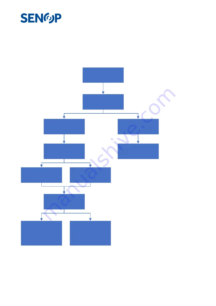
A typical use case scenario is shown on the flow chart image below. All the necessary actions are discussed 

in more detail in the text. 


Connecting to the HSC-2 

Power up the HSC-2 device by connecting the DC Voltage cable and connect the Ethernet cable between the 

HSC-2 and a PC. Start the Senop HSI-2 Software. On the 

Device

 tab, press the + sign. On the opened window, 

Connect the camera to 

the HSI-2 software

Create a 

Sequence

Create a measurement 

Script

Take a 

Snapshot

Record the script with 

the HSI-2 software

Record the script using 

the device UI

Import the data to the PC 

using the HSI-2 software

Upload the script to the 

HSC-2 camera

Click anywhere on the 

image to see th e 

spectrum

Open the data sequence 

on the HSI-2 software 

and click anywhere on 

the image to see the 

spectrum

Analyze the data u sing 

3rd party software

Содержание HSC-2

Страница 1: ...Senop Hyperspectral Camera HSC 2 User Guide Version 30 5 4 2019 DRAFT...

Страница 2: ...S FOR A PARTICULAR PURPOSE AND NONINFRINGEMENT OR ARISING FROM A COURSE OF DEALING USAGE OR TRADE PRACTICE IN NO EVENT SHALL SENOP OR ITS SUPPLIERS BE LIABLE FOR ANY INDIRECT SPECIAL CONSEQUENTIAL OR...

Страница 3: ...ment 8 Open Source Software Notice 8 Specifications 9 Powering 9 Operation conditions 9 Optics 9 Imaging capability 9 Spectral capability 9 Connections 10 Peripherals 10 Device UI 10 Sales Package Con...

Страница 4: ...zation 22 Sequence slider 22 Exposure setting Add to Script 22 Script Creator 23 Quick start guide 25 Connecting to the HSC 2 25 Taking a snapshot using the default Sequence 26 Creating and measuring...

Страница 5: ...or almost same object or landscape is represented with multiple narrow band wavelengths The Senop Hyperspectral camera can work independently with only power supplied to it with integrated memory or i...

Страница 6: ...ol a cross out wheeled waste bin with a bar beneath as below The full text of the EU declaration of conformity is available at the following internet address http senop fi compliance FCC FCC Informati...

Страница 7: ...ated or preheated air Keep your device away from radiators and heat sources Keep your equipment away from extremely hot or cold temperatures to ensure that it is used within the specified operating ra...

Страница 8: ...ulting from misuse unauthorized modification operation or storage outside the environment specification for the product or in transit damage Open Source Software Notice This product contains Senop HSI...

Страница 9: ...ll be inhibited to prevent damages Relative humidity less than 85 not condensing Optics F 3 28 FOV 36 8 deg Focus distance 30cm to limited FOV with less than 30cm distances Imaging capability Image fr...

Страница 10: ...S o Internal antenna is located next GPS connector facing up o External antenna not included thru MMCX connector for GPS and Glonass Integrated IMU o Accuracy typically 1 Device UI Display o Resolutio...

Страница 11: ...11 25247 o Customized Peli 1400...

Страница 12: ...tral Camera is not controlled directly by computer there are certain functions that can be operated from the device own user interface Run script Single shot Settings for o Time and Date o Ethernet o...

Страница 13: ...pply 7 17V 20W Ethernet RJ 45 USB C Mini DisplaPort External GPS antenna MMCX AUX connector There are six connectors on the device Ethernet RJ 45 connector Power connector USB connector Display port c...

Страница 14: ...ge to the device Recommended Operating Conditions o Supply voltage 1 65V 5 5V o High level input voltage When VccI is 1 65 to 1 95V Min VccI 0 65V When VccI is 2 3 to 2 7V Min 1 7V When VccI is 3 to 3...

Страница 15: ...r interface is supplied TRIG pin should be kept all the time in either GND or IO Power voltage 1 65V 6 5V o This can be done for example ON ON type control o TRIG pin is tied to GND with 10k resistor...

Страница 16: ...m water o Hyperspectral imaging during rain will not work Mechanical fixing There is a UNC 20 mounting thread installed in device aluminum base plate It is advisable to attach baseplate directly again...

Страница 17: ...UX connector USB connector Ethernet or Mini DisplayPort if supported by the drone gimbal Power connector type in cable Barrel Plug 2 5mm I D x 5 5mm O D Positive Center GPS in Drone Use Internal Anten...

Страница 18: ...sed to image from a great distance it is useful to consider the affect of the resolution of the image The graph below shows the size what one pixel sees at a given imaging distance For example when th...

Страница 19: ...19 25247 0 10 20 30 40 50 60 70 0 10 20 30 40 50 60 70 80 90 100 Size seen by a frame m Imagingdistance m...

Страница 20: ...Viewing live image for camera Data browsing Data visualization Sequence editing Script editing Device configuration and updating HSI Data Visualization view In HSI 2 Data Visualization view it is poss...

Страница 21: ...pen data o Opens file manager Snapshot o Pause Play Visualization area Live stream False RGB or Grayscale Snapshot still image paused from live stream with defined sequence Saved data opened from file...

Страница 22: ...Edit Opens currently selected sequence to the sequence editor for editing sequence Clear all Clears all sequences from the sequence list except default sequence Add to script Lists sequence to the se...

Страница 23: ...23 25247 Script Creator...

Страница 24: ...nal trigger rising o External trigger decreasing Not supported by the software at the moment o Delay Sequence measure occurrence Number of occurrences or infinite occurrence Sequence interval Interval...

Страница 25: ...2 Software On the Device tab press the sign On the opened window Connect the camera to the HSI 2 software Create a Sequence Create a measurement Script Take a Snapshot Record the script with the HSI 2...

Страница 26: ...op right corner there is a Visualization window which shows the selected wavelengths for the sequence There is a default sequence shown which has 13 measurement points i e frames between 400 nm 1000 n...

Страница 27: ...op right corner of the HSI 2 software To create a new sequence click the button from the Sequence window and select New In the opened window select desired wavelength range number of measurement point...

Страница 28: ...s to be measured within the script and the SEQUENCE INTERVAL parameter defines what is the time interval between adjacent measurements Multiple sequences can be added to a script and their order can b...

Страница 29: ...e for starting the recording Once the recording is done press OK and back buttons to navigate to the main menu The HSC 2 camera has a Display port which can be used to transfer the video to and extern...

Страница 30: ...in HSI 2 software To open the stored data cube press the open icon at the DATA VISUALIZATION sheet Select the desired sequence from the folder and click OK The data cube opens and the spectrum can be...

Страница 31: ...es 0 000542 0 000557 These values are used to convert integer values in cube to SI unit different for each image etc Free programs are available to open ENVI files as there is libraries to handle ENVI...

Страница 32: ...Acquisition time of the bands compared to the first measurement in nanoseconds senop sensor N A N A N A N A N A Used sensor N A senop frame counter 0 1 3 4 2 Order at which the bands are measured sen...

Страница 33: ...e xz package should be extracted first and then the tar package After the extraction connect the HSC 2 camera to the computer using the Ethernet cable and connect the camera to the HSI 2 software From...

Отзывы: