background image

MI00205-7-EN

INSTALLATION MANUAL

2/4

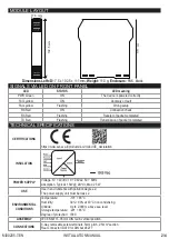
MODULE LAYOUT

Dimensions LxHxD

 17.5 x 102.5 x 111 mm; 

Weight:

 110 g; 

Enclosure:

 PA6, black

17.5 mm

111
 m

m

102.5 mm

LED

STATUS

LED meaning

PWR Green

ON

The device is powered correctly

FAIL yellow

ON

Anomaly or fault

FAIL yellow

Flashing

Wrong setup

RX Red

ON

Connection check

RX Red

Flashing

Receipt of packet completed

TX Red

Flashing

Transmission of packet completed

SIGNALS VIA LED ON FRONT PANEL

TECHNICAL SPECIFICATIONS

CERTIFICATIONS

https://www.seneca.it/products/z-d-in/doc/CE_declaration

INSULATION

POWER SUPPLY

Voltage: 10 ÷ 40Vdc; 19 ÷ 28Vac; 50 ÷ 60Hz

Absorption: Typical: 1.5W @ 24Vdc, Max: 2.5W

USE

Use in environments with pollution degree 2.

The power supply unit must be class 2.

ENVIRONMENTAL 

CONDITIONS

Temperature

-10÷ + 65°C


Humidity

30%÷ 90% at 40°C non condensing.

Altitude: 

Up to 2,000 m above sea level


Storage temperature:

  -20÷ + 85°C


Degree of protection: 

IP20.

ASSEMBLY

IEC EN60715, 35mm DIN rail in vertical position.

CONNECTIONS

3-way removable screw terminals, 5mm pitch, 2.5mm

2

 section

Rear connector IDC10 for DIN bar 46277

Содержание Z-D-IN

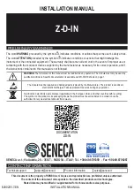
Страница 1: ...ke appropriate measures during any operation PRELIMINARY WARNINGS The word WARNING preceded by the symbol indicates conditions or actions that put the user s safety at risk The word ATTENTION preceded by the symbol indicates conditions or actions that might damage the instrument or the connected equipment The warranty shall become null and void in the event of improper use or tampering with the mo...

Страница 2: ...T PANEL TECHNICAL SPECIFICATIONS CERTIFICATIONS https www seneca it products z d in doc CE_declaration INSULATION POWER SUPPLY Voltage 10 40Vdc 19 28Vac 50 60Hz Absorption Typical 1 5W 24Vdc Max 2 5W USE Use in environments with pollution degree 2 The power supply unit must be class 2 ENVIRONMENTAL CONDITIONS Temperature 10 65 C Humidity 30 90 at 40 C non condensing Altitude Up to 2 000 m above se...

Страница 3: ...on length Module Module Module Module Module 3 Bus length Ld derivation length ModBUS CONNECTION RULES 1 Install the modules in the DIN rail 120 max 2 Connect the remote modules using cables of an appropriate length The following table shows cable length data Bus length maximum length of the Modbus network according to the Baud Rate This is the length of the cables that connect the two farthest mo...

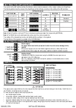
Страница 4: ...ine with a value suitable to what the situation requires ModBus RS485 Connection for RS485 communication using the MODBUS master system as an alternative to the Z PC DINx bus N B The indication of the RS485 connection polarity is not standardised and in some devices may be inverted INPUTS 1 11 12 7 8 9 10 1 2 3 4 5 Z D IN 1 16V 1 11 12 7 8 9 10 1 11 12 7 8 9 10 PNP NPN 1 2 3 4 5 1 2 3 4 5 R 1k5 1k...

Отзывы: