ENGLISH 4/8
MI0
-E
03342
The module is designed to be installed on DIN46277 rail in vertical position.
4.0 PRELIMINARY INSTRUCTIONS FOR USE
It is forbidden to place anything that could obstruct the ventilation slits.
It is forbidden to install the module near heat sources.
«Severe operating conditions» are defined as follows:
- High power supply voltage: exceed 30Vdc or exceed 26 Vac
- The module power the sensor.
If the modules are installed side by side,
in the following cases:
separate them by at least 5mm
- the operating temperature exceed 45°C and at least one of the severe operating conditions exist;
- the operating temperature exceed 35°C and at least two of the severe operating conditions exist.
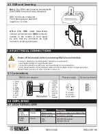
4.1 Installation and removal on DIN46277 rail
INSTALLATION:
1) Pull the four latches (placed in the backside panel) outwards;
2) Insert the module in a DIN46277 rail free slot;
3) Make sure that the IDC10-connector pins
are inserted on the slot correctly;
4) Press the four latches inwards.
REMOVAL:
1) Pull the four latches (placed in the backside
panel) outwards, using a screwdriver.
2) Pull out the module gently.
It’s important to insert the pins on the slot correctly because IDC 10-connector is polarized;
this connection is facilitied by use of a female/male insertion between IDC10 connector and DIN rail slot.
. Power supply from rear IDC10 Connector
(Fig. 1c and Fig. 1d)
.
4.2 Use Z-PC-DINAL accessory
Z-MODEM
GSM
POWER
GSM
STATUS
Z-MODEM
GSM
POWER
GSM
STATUS
Содержание Serie Z PC
Страница 7: ...ENGLISH 7 8 MI00 E 3342...
Страница 8: ...ENGLISH 8 8 MI0 E 03342...


