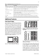
Schweitzer Engineering Laboratories, Inc.
SEL-487B Data Sheet
19
Monitoring and Metering
Access a range of useful information in the relay with the
metering function. Metered quantities include
fundamental primary and secondary current and voltage
magnitudes and angles for each terminal. Secondary
quantities also include the PT ratio and CT ratio of each
terminal. Zone information displays primary current and
voltage magnitudes and angles for each terminal and also
includes the polarity of each CT and the bus-zones in
each of the protective zones at the station. The same
information is available in secondary quantities and
includes both the CT ratio and polarity. Differential
metering shows the operating and restraint currents, as
well as the reference current, for each zone.
Event Reporting and Sequential
Events Recorder (SER)
Event Reports and Sequential Events Recorder features
simplify post-fault analysis and help improve your
understanding of both simple and complex protective
scheme operations. These features also aid in testing and
troubleshooting relay settings and protection schemes.
Oscillography and Event Reporting
In response to a user-selected internal or external trigger,
the voltage, current, and element status information con-
tained in each event report confirms relay, scheme, and
system performance for every fault. The SEL-487B pro-
vides sampling rates as fast as 8 kHz for analog quanti-
ties in a COMTRADE file format. It also provides 12
sample-per cycle and 4 sample-per-cycle event reports
that sample filtered analog quantities. The relay stores in
nonvolatile memory as much as 5 seconds of 8 kHz event
data and as much as 24 seconds of 1 kHz event data.
Relay settings operational in the relay at the time of the
event display at the end of each filtered event report.
Use event report settings in the relay to assign up to 20
analog quantities for inclusion in the filtered event
reports. Use relay-calculated values such as check zone
operate and restraint current, or use SEL
OGIC
automation
or protection math variables.
Each SEL-487B provides event reports for analysis with
software such as the
AC
SEL
ERATOR
Analytic Assistant
®
SEL-5601 Software. With
AC
SEL
ERATOR
Analytic
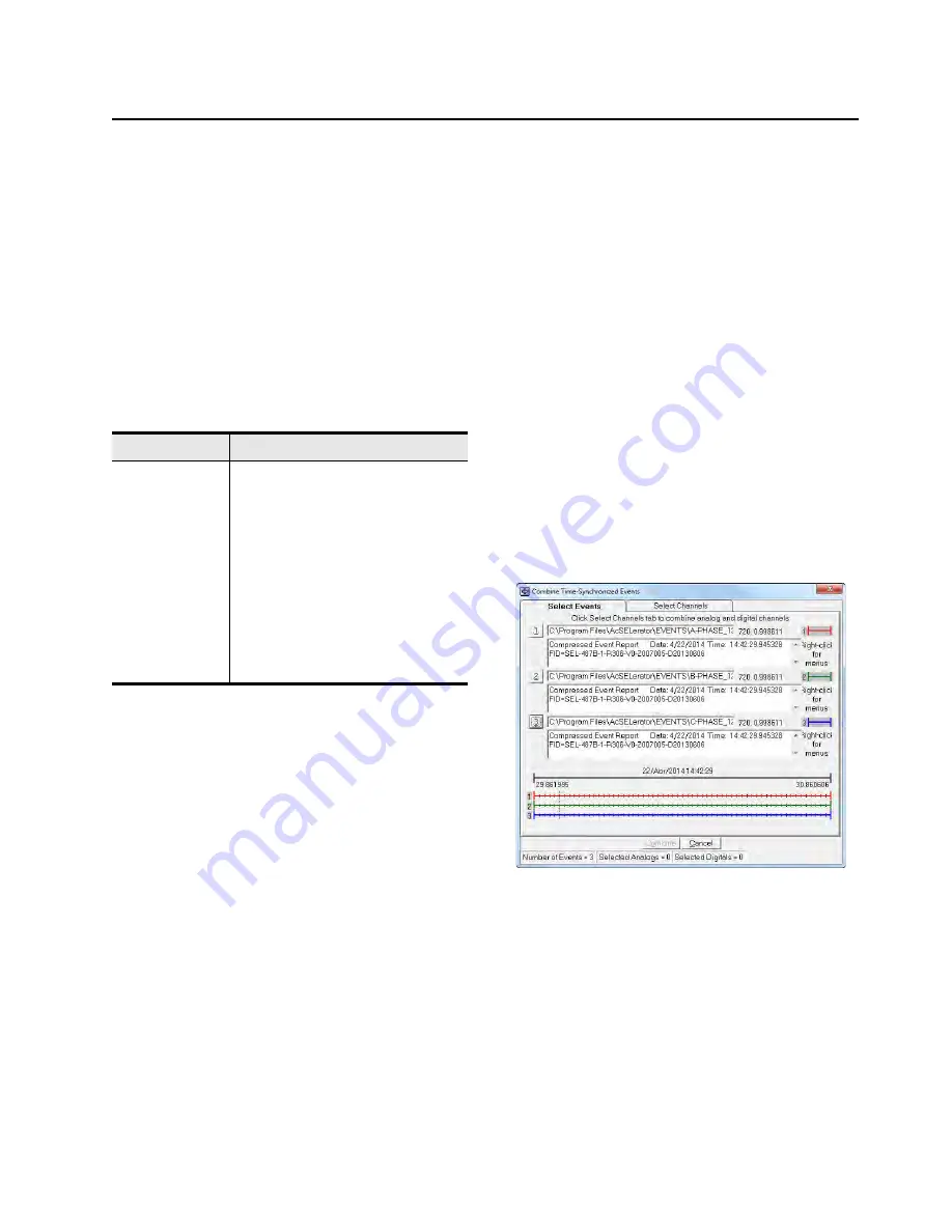
Assistant, you can display events within the same time-
stamp range from as many as three different relays in one
window to make fault analysis easier and more
meaningful. Because different relays time-stamp events
with values from their individual clocks, be sure to time
synchronize the SEL-487B with an IRIG-B clock input
before using this feature (see Figure 20). Figure 30
shows the SEL-5601 software screen with three events
selected.
Figure 30
Software Screen After Reading an Event
From Three Different Relays
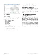
Select from each event the information of interest, and
combine this selection into a single window. Figure 31
shows the combination of the tie-breaker A-phase current
(Relay 1), B-phase current (Relay 2), and C-phase
current (Relay 3) in one window.
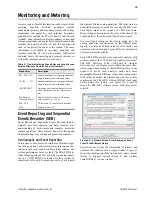
Table 9
Flexible Metering Capabilities and Large Screen
Display Eliminate Need for Panel Instruments
Capabilities
Description
V01, V02, V03
Fundamental phase voltage magnitude and
angle in primary and secondary values
I01, I02, . . ., I21
Fundamental phase current magnitude and
angle in primary and secondary values
IOP, IRT, IREF
Operating and restraint currents for each
zone, check zone, and the reference cur-
rent
Bus Zones in
Protection Zone n
Names of the bus-zones in Protection
Zone n (where n = 1 to 6)
PTR, CTR
PT ratio and CT ratio for each terminal
POL
Polarity of each CT


