


H.2
SEL-751A Relay
Instruction Manual
Date Code 20100129
Synchrophasors
Synchrophasor Measurement
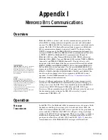
The SEL-3306 Synchrophasor Processor is a PC-based communications
processor specifically designed to interface with PMUs. The SEL-3306 has
two primary functions. The first is to collect and correlate synchrophasor data
from multiple PMUs. The second is to then compact and transmit
synchrophasor data either to a data historian for post-analysis or to
visualization software for real-time viewing of a power system.
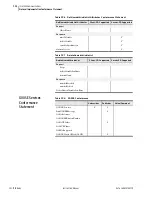
The SEL-751A supports the protocol portion of the IEEE C37.118, Standard
for Synchrophasors for Power Systems. In the SEL-751A, this protocol is
referred to simply as C37.118. See
Settings Affect Message Contents on
.
Synchrophasor Measurement
The phasor measurement unit in the SEL-751A measures four voltages (V
A
,
V
B
, V
C
, and V
sync
) and four currents (I
A
, I
B
, I
C
, and I
N
) on a constant-time
basis. These samples are time-stamped with the IRIG time source. The phase
angle is measured relative to an absolute time reference, which is represented
by a cosine function in
. The time-of-day is shown for the two time
marks. The reference is consistent with the phase reference defined in the
C37.118 standard. During steady-state conditions, the SEL-751A
synchrophasor values can be directly compared to values from other phasor
measurement units that conform to C37.118. Synchrophasor values are
available for the full frequency range of the SEL-751A.
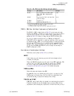
Figure H.1
Phase Reference
The TSOK Relay Word bit asserts when the SEL-751A has determined that
the IRIG-B time source has sufficient accuracy and the synchrophasor data
meets the specified accuracy. Synchrophasors are still measured if the time
source threshold is not met, as indicated by Relay Word bit TSOK = logical 0.
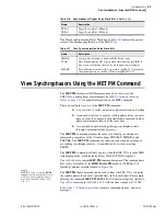
The
MET PM
command is not available in this case.
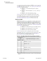
The instrumentation transformers (PTs or CTs) and the interconnecting cables
may introduce a time shift in the measured signal. Global settings VCOMP
and ICOMP, entered in degrees, are added to the measured phasor angles to
create the corrected phasor angles, as shown in
,
, and
. The VCOMP and ICOMP settings may be positive or negative
values.
t
10:00:00:000000
10:00:00:016667
Содержание 751A
Страница 1: ...20100129 SEL 751A Feeder Protection Relay Instruction Manual PM751A 01 NB...
Страница 6: ...This page intentionally left blank...
Страница 12: ...This page intentionally left blank...
Страница 18: ...This page intentionally left blank...
Страница 26: ...This page intentionally left blank...
Страница 92: ...This page intentionally left blank...
Страница 218: ...This page intentionally left blank...
Страница 250: ...This page intentionally left blank...
Страница 376: ...This page intentionally left blank...
Страница 392: ...This page intentionally left blank...
Страница 408: ...This page intentionally left blank...
Страница 418: ...This page intentionally left blank...
Страница 434: ...This page intentionally left blank...
Страница 462: ...This page intentionally left blank...
Страница 544: ...This page intentionally left blank...
Страница 580: ...This page intentionally left blank...
Страница 584: ...This page intentionally left blank...
Страница 632: ...This page intentionally left blank...
Страница 636: ...This page intentionally left blank...
Страница 640: ...This page intentionally left blank...


