


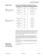


4.96
SEL-751A Relay
Instruction Manual
Date Code 20100129
Protection and Logic Functions
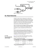
Arc-Flash Protection
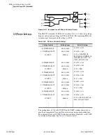
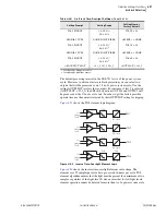
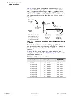
The arc-flash overcurrent elements use raw A/D converter samples, with the
sampling rate of 16 samples per cycle. Individual samples are compared with
the setting threshold as shown in
, followed by a security counter
requiring that two samples in a row be above the setting threshold. Although
both elements operate on instantaneous current values, additional scaling is
applied to present settings in the user-friendly “rms” format.
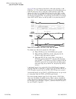
Fast overcurrent detectors do not reject harmonics and therefore have a natural
tendency to “overreach” under high harmonic load conditions. To avoid
unintended element pickup, Arc-flash trip level 50PAFP should be set at least
2 times the expected maximum load. Temporary activation of the arc-flash
overcurrent element during inrush / load pickup conditions is expected and
will normally be taken into account by the arc-flash “light based” supervision.
Figure 4.52
Arc-Flash Instantaneous Overcurrent Element Logic
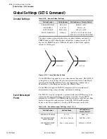
Arc-Flash Time-
Overlight Elements
(TOL1 through TOL4)
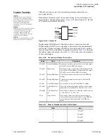
The SEL-751A relay offers four fiber-optic light sensor inputs. Each input is
associated with one inverse time-over light element offering enhanced security
coupled with exceptionally fast operation. Shape of the inverse time
characteristic is fixed offering robust rejection of unrelated light events
without adding unnecessary settings.
shows the arc-flash time-
overlight element settings.
Each sensor channel has a user selectable sensor type (NONE, POINT, or
FIBER) representing the type of sensor installed. Keyword POINT is used to
represent a point sensor, while the keyword FIBER represents a bare fiber
loop sensor.
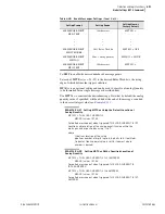
TOL Pickup parameter makes it possible to set the individual light threshold
levels for each of the 4 sensors. Pickup level is expressed in the percent of full
scale, which is directly related to the light intensity level measured by the
sensor.
When required, channel sensitivity can be compared to a light intensity level
expressed in lux as shown in
. However, due to light sensitivity
being associated with fiber length (which is installation dependent), TOL
element settings are expressed as a percentage of the available A/D converter
range.
2
16
50PAF
Relay
Word
Bit
2
16
2
16
IA Sample
IB Sample
IC Sample
Setting 50AFP
Scaled to
Equivalent Sample
50PAF Element Shown, 50NAF Element is Similar
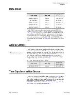
Table 4.44
Arc-Flash Time-Overlight Settings
(Sheet 1 of 2)
Setting Prompt
Setting Range
Setting Name :=
Factory Default
SENSOR 1 TYPE
NONE, POINT, FIBER
AFSENS1 := NONE
TOL 1 PICKUP
3.0–20.0 %
a
0.6–4.0 %
b
TOL1P := 5.0
SENSOR 2 TYPE
NONE, POINT, FIBER
AFSENS2 := NONE
Содержание 751A
Страница 1: ...20100129 SEL 751A Feeder Protection Relay Instruction Manual PM751A 01 NB...
Страница 6: ...This page intentionally left blank...
Страница 12: ...This page intentionally left blank...
Страница 18: ...This page intentionally left blank...
Страница 26: ...This page intentionally left blank...
Страница 92: ...This page intentionally left blank...
Страница 218: ...This page intentionally left blank...
Страница 250: ...This page intentionally left blank...
Страница 376: ...This page intentionally left blank...
Страница 392: ...This page intentionally left blank...
Страница 408: ...This page intentionally left blank...
Страница 418: ...This page intentionally left blank...
Страница 434: ...This page intentionally left blank...
Страница 462: ...This page intentionally left blank...
Страница 544: ...This page intentionally left blank...
Страница 580: ...This page intentionally left blank...
Страница 584: ...This page intentionally left blank...
Страница 632: ...This page intentionally left blank...
Страница 636: ...This page intentionally left blank...
Страница 640: ...This page intentionally left blank...


