32
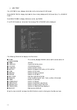
c. JVS TEST
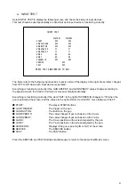
The JVS TEST screen displays information on the connected JVS I/O boards.
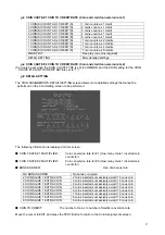
Select INPUT TEST to display input data for the currently displayed JVS I/O board. (See “d - JVS INPUT
TEST”)
Select NEXT NODE to display information on the next NODE.
If no JVS I/O boards are connected, the message “NO JVS NODE” will be displayed.
The following information is displayed on this screen.
●
NODE:
The currently displayed NODE number and the total number of
connected NODEs
●
NAME:
ID Code
●
CMD VER:
Command format version
●
JVS VER:
JVS standard version
●
COM VER:
Communication version
●
SWITCH:
Number of players and number of 1P switches
●
COIN:
Number of coin slots
●
ANALOG:
Number of analog channels
●
ROTARY:
Number of encoders
●
KEYCODE:
Keycode input active/inactive
●
SCREEN:
Screen position input (X axis, Y axis, number of channels)
●
CARD:
Number of card slots
●
HOPPER OUT:
Number of hoppers
●
DRIVER OUT:
Number of standard output drivers
●
ANALOG OUT:
Number of analog output channels
●
CHARACTER:
Number of characters/lines displayed
●
BACKUP:
Backup present/absent
Move the cursor to EXIT and press the TEST Button to return to the System Test Menu screen.
Содержание MINI DELUXE THE HOUSE OF THE DEAD 4
Страница 8: ...6 4 NAME OF PARTS Width cm Depth cm Height cm Weight kg When Assembled 76 5 140 5 197 5 Approx 180...
Страница 74: ...72 11 CONTROLLER UNIT GUN...
Страница 76: ...74...
Страница 77: ...75...
Страница 78: ...76...
Страница 79: ...77...
Страница 94: ...92 17 5 ASSY MONITOR UK HDF 1070UK...
Страница 103: ...101 19 APPENDIX A ELECTRICAL SCHEMATIC The following page contains the electrical schematic for this machine...
Страница 104: ......
Страница 105: ......
Страница 106: ......

