


3.
ELECTRICAL INSTALLATION
3.1 General
The Controller meet requirements for
Í
-marking according to EN 55022 (1998) + A1 + A2 and EN 61000-4-3
(2006). In order to ensure maximum EMC-protection and CE-compatibility, it is required that the cable installation
instructions are strictly adhered to.
3.2 Terminal connections
The procedure which must be observed in connecting electrical cables to SEG's weighing systems is described
below.
The weighing system utilizes different cable types.
- Power cable for main voltage to the scale controler.
- Signal cable for connection of load cells.
- Control cables for output relays.
- Signal cable 0/4-20mA output to auxiliary equipment (PLC, PC, printer, remote indicator etc.).
- Signal cable for serial communication RS485 to auxiliary equipment (PLC, PC, Indicator etc.).
Signal cables must be laid with great care to ensure faultless operation of the weighing system. Signal cables may
not be laid near any kind of high power cable. Thus, they may not be laid in a common conduit or a common cable
trough. Signal cables parallel to power cables must be separated by at least 2 m when distance exceeds a few
metres. Shielded cables must be used for all installations, and care must be taken to ensure that the shield is
properly connected inside the cable glands, so that the shield gets proper contact with the controller enclosure.
Signal cable splicing should be avoided. Junction and connection boxes must not permit the entry of any
moisture. Cable clamps must be used for all cables.
18-08-16
S44-H15E
3-1
S-E-G
SYSTEM A2-H15 INSTRUCTION
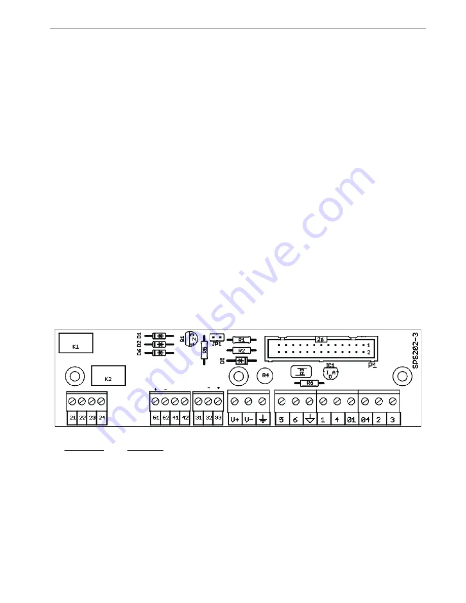
Fig.3.1, Terminal locations
Terminal no.
Description
1,01,2,3,4,04
Load cell signal input 0-45mVdc, max 140mA/85 Ohms. Ref. to section 3.3 - 3.4.
5(-), 6(+)
Speed/pulse sensor input; S-E-G type F, Relay dry contact or NPN proximity switch.
V+, V-, Ground
Power supply 24Vdc (13-30Vdc). Optional 90-230Vac/24Vdc module (PW-24) available.
31, 32, 33
1 RS485 serial port. 31(Gnd), 32(TRx-), 33(TRx+) Ref. to section 3.5.
41,42
1 Digital input for belt position sensor. Contact closure or Proximity switch (NPN or PNP).
51(+),52(-)
Analog output 4-20mA (Flowrate), max 350 Ohms.
21,22,23,24
2 Relay ouputs, closing contacts (NO) 24Vdc/1A.
21,22: Totaliser pulse. 23,24: Selectable; Belt running, Flow level, Speed level or Load level.


