42 |
APPENDICES
Reassembly of the Cooler
Important! Carefully follow steps 21 to 42 in order to
correctly reassemble the cooler.
20. Install the drain valve. Refer “INSTALLING THE DRAIN
VALVE” on page 20
21. Transport the plenum assembly to the roof and then
connect it to the supply venturi assembly on the dropper.
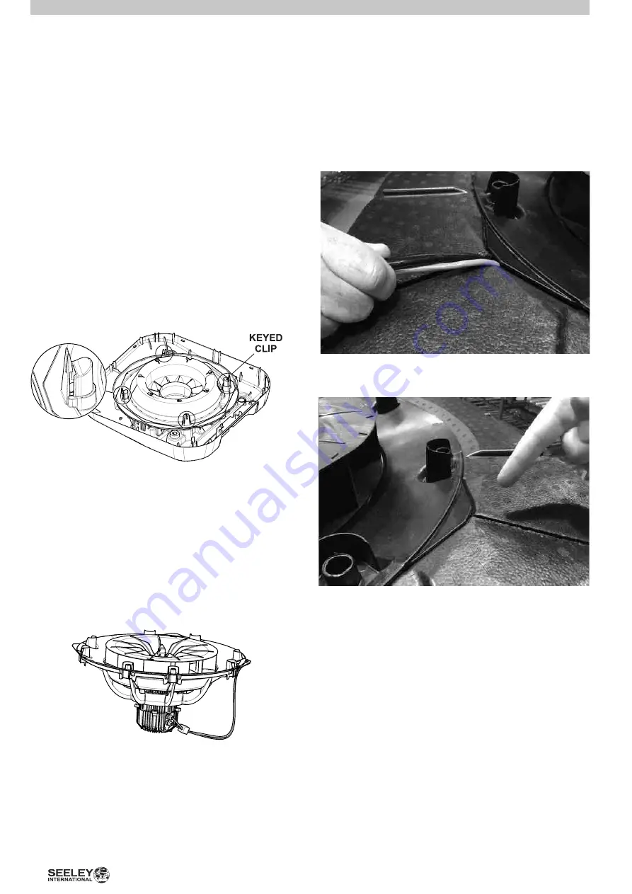
There are 4 female clips on the legs of the plenum
assembly which engage with the 4 male clips on the
supply venturi. The male clip closest to the drain valve is
keyed and will only engage when the plenum assembly
is orientated correctly.
Important!
Be sure to be careful
with the clips! Make sure they are properly aligned before
attempting to engage. Do not force the clips! Excessive
force may cause them to break.
ILL3126-A
22.
Important! Check to make sure that the foam plenums
are firmly and correctly fitted to the plenum inner as
this forms a sealing face.
23. Transport the top motor/fan assembly to the roof.
Important!
This assembly is bulky and weighs 22kg. Use
the appropriate mechanical aids and lifting technique to
avoid injury.
The assembly is keyed to ensure the motor cable exits to
the correct orientation in the cooler.
Reinstall electronics enclosure in its original position and
secure with the clips and screw.
24. Install top motor/fan assembly to the top of the plenum in
reverse order of that specified in step 5. Ensure cables are
oriented towards the electronics enclosure location and re-
secure cables using cable ties. Lift the top fan assembly up
and locate the assembly onto the plenum spigots.
27. Switch isolator on the electronics enclosure to the “ON”
position when ready. Clip the electronics cover back in
place.
28. When cooler operation has been verified, carefully
transport side panels with filters to cooler location and
attach them to cooler in reverse of disassembly process.
Re-fit clips to secure side panels
ILL3120-A
ILL2810-A
25. Be sure to direct the motor cables through the gap in the
foam plenum. Ensure the top motor/fan assembly forms a
good seal with the foam and that the cables are sitting in
their dedicated slots.
26. There should be no gap between the foam and top fan
assembly.
ILL2810-A
APPENDIX – B ‘PIECE BY PIECE’ INSTALLATION


