background image

8

CHIMNEY INSTALLATION

G

ENERAL 

N

OTES

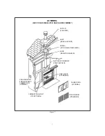
1.

The Security fireplaces are listed only with Security Chimneys International Ltd systems.  

Do not connect the

fireplace to a masonry chimney, chimney liner, or other brand of metal chimney

.

2.

The chimney models and of Oliver MacLeod, division of Security Chimneys International
Ltd are respectively equivalent to models ASHT+ and S-2100+.

3.

In areas with continuous temperatures below 0

F (-18

C) the use of an exterior chimney increases the

likelihood of operating problems such as low draft, high rate of creosoting and poor start-up characteristics.
Exterior chimneys are also prone to down-drafting and flow reversal.  Installations which are located low in the
house such as in a basement, in combination with outside chimneys, are especially prone to flow reversal.  In
cold areas, air cooled chimneys should not be used in an exterior installation.

4.

A chimney venting a fireplace shall not vent any other appliance.

5.

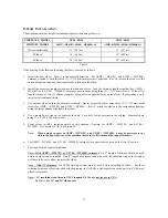
The minimum system height, including the fireplace is the following:

Table 1

FIREPLACE MODEL

SE36  

/  

SB36

SB42 

/  

SR42

CHIMNEY MODEL

ASHT+ 

, S-2100+ 

or AC

VERTICAL INSTALLATION

4.57 m (15’)

4.57 m (15’)

ONE OFFSET

5.49 m (18’)

5.49 m (18’)

TWO OFFSETS

6.10 m (20’)

6.10 m (20’)

6.

In altitude, add 18" (450 mm) to the chimney for every 2000 ft. (600 m) above sea level.

WARNING

:

In cold areas, an air cooled chimney may generate large amounts of water due to condensation.  This water will
accumulate on top of the fireplace and may cause corrosion.  Security Chimneys International Ltd cannot be
held responsible for condensation and corrosion problems.  In cold climates, Security Chimneys International
recommends the use of ASHT+ / or S-2100+ / chimneys.

7.

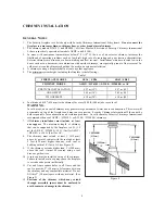
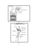
All chimney installations must include  at least
one support.  

The maximum length of chimney

that can be supported by the fireplace is 6 ft. (1.8
m) for S-2100+ / , 10 ft. (3m) for ASHT+
/ or 26 ft. (8 m) for AC.

8.

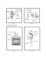
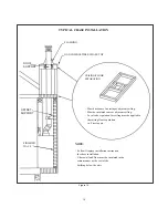
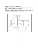
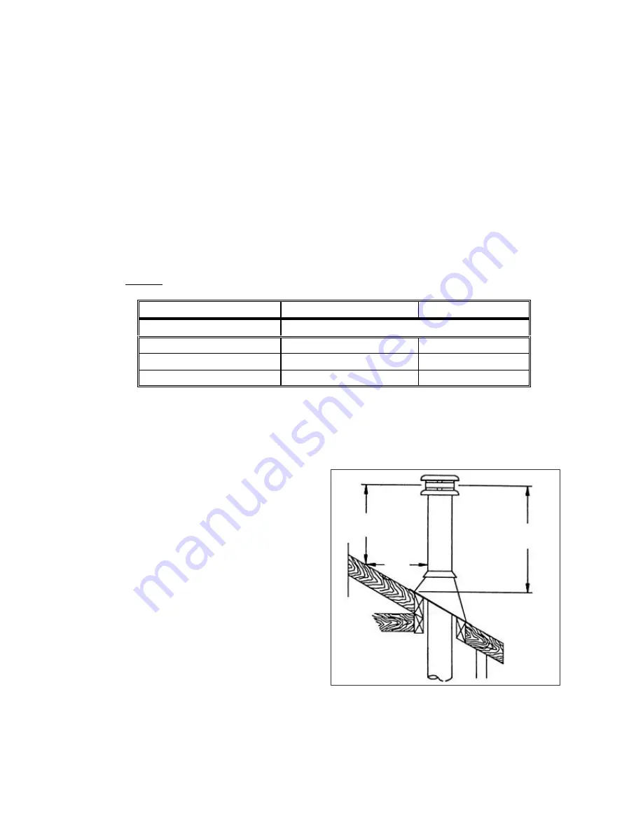
The chimney must extend at least 3' (915 mm)
above its point of contact with the roof and at least
2 feet (610 mm) higher than any wall, roof or
building within 10' (3 m) of it. (see Figure 8)

9.


If the chimney extends higher than 5' (1500 mm)
above the roof, it must be secured using a roof
brace or guide wires.

10. A rain cap must be installed on top of the chimney.

Failure to install a rain cap may cause the fireplace
to corrode and operate inefficiently.

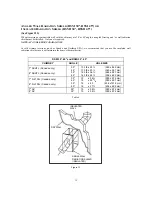
11. Cut and frame square holes in all floors and the

roof to provide 2" (50 mm) of clearance between
the chimney and any combustible material.  Do not
fill this 2" (50 mm) space with any material. (See
Figure 9)

12.

Portions of the chimney which may extend
through accessible spaces must be enclosed to
avoid contact or damage to the chimney

.

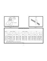
2' MINIMUM

(610mm)

3' MINIMUM

(915mm)

(3000mm)

10'

Figure 8

Содержание SB36

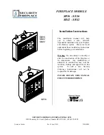
Страница 1: ...ctions before beginning your installation Warning Do not attempt to modify or alter the construction of the fireplace or its components Any modification or alteration of construction may void the warranty listings and approvals of this system In such a case Security Chimneys International will not be responsible for damages PLEASE RETAIN THIS MANUAL FOR FUTURE REFERENCE SECURITY CHIMNEYS INTERNATI...

Страница 2: ...i W a r n o CERTIFICATION LABEL ...

Страница 3: ...ional Ltd will provide replacement parts if available at 50 of the retail price except the parts mentioned above Security Chimneys International Ltd shall not be responsible for any labour costs 4 The following partsare not covered by the warranty tempered glass doors brass trims panels louvers This warranty may not be extended by our representatives in any manner whatsoever Warrantor makes no war...

Страница 4: ...ure 4 Facing and Mantel 4 Hearth Extension Requirements 5 Outside Air Installation 5 Chimney Installation General Notes 8 Straight Installation 9 Offset Installation 11 Angled Wall Radiation Shield Insulated Radiation Shield 15 Universal Roof Support Installation 16 Universal Offset Support Installation 16 Chimney Chase and Multiple Terminations 17 Parts and Components 18 Decorative Trims and Pane...

Страница 5: ...posed of by burial in soil or otherwise locally dispersed they should be retained in the closed container until all cinders have thoroughly cooled CAUTION Never leave children unattended when there is a fire burning in the fireplace CAUTION This fireplace has been tested with Security Chimneys International Ltd wood grates They must always be used CAUTION Keep combustible material at least 48 away...

Страница 6: ...y to clean your chimney 2 Have your chimney cleaned by a qualified chimney sweep If you wish to clean it yourself we recommend using a stiff plastic or non metallic brush If a metal brush is used its size should be slightly smaller than the flue to avoid damaging the chimney Do not use a brush that could scratch the stainless steel interior of the chimney 3 Do not expect chemical cleaners to keep ...

Страница 7: ...eration 8 Failure to use parts manufactured by Security Fireplace or variations in techniques and construction materials described in this installation manual may create a serious fire hazard it may void the Security Fireplace warranty and will void the WHI listing 9 The Security fireplace features optional glass doors outside combustion air kit blowers and decorative trims and panels TOOLS AND BU...

Страница 8: ... wall 2 IN CANADA the fireplace must be installed against a finished wall It must not be installed against a vapour barrier or exposed insulation 3 The fireplace is zero clearance Combustible material like wood plywood particle board or drywall can be in direct contact with the fireplace wall or the fireplace top spacer Two inch 50 mm clearance to combustibles must be kept around the chimney 4 Do ...

Страница 9: ...otential problem we recommend installing an OUTSIDE AIR assembly and glass doors The fireplace s outside air control should be open when the fireplace is being used The outside air control is located behind the fireplace s lower louver Pull this lever to open The OUTSIDE AIR assembly for fireplaces and air cooled chimneys is mandatory in some areas Check with your local building authority for the ...

Страница 10: ...LATION ALUMINUM TAPE FLEXIBLE ALUMINUM DUCT WALL OPEN SIDE DOWN PLASTIC COVERED INSULATION OUTSIDE AIR CONNECTOR FIREPLACE ALUMINUM TAPE FLEXIBLE ALUMINUM DUCT 2 MIN CLEARANCE PLYWOOD OR DRYWALL 2 X 3 FRAME CAP STORM COLLAR ROOFSUPPORT FLASHING ATTIC RADIATION SHIELD FIRESTOP ASHT CHIMNEY RADIATION RING ...

Страница 11: ...FA F FLASHING ACST ROOF SUPPORT ACRSA ATTIC RADIATION SHIELD ACRS RADIATION SHIELD AIR COOLED CHIMNEY STARTING PIECE FIRE GRATE STANDARD GLASS DOOR OPTIONAL FIRE SCREEN STANDARD COOLING AIR KIT FOR AIR COOLED CHIMNEY ACZI OPTIONAL COMBUSTION AIR KIT UZI OPTIONAL ...

Страница 12: ...ney for every 2000 ft 600 m above sea level WARNING In cold areas an air cooled chimney may generate large amounts of water due to condensation This water will accumulate on top of the fireplace and may cause corrosion Security Chimneys International Ltd cannot be held responsible for condensation and corrosion problems In cold climates Security Chimneys International recommends the use of ASHT HT...

Страница 13: ...ection should be the first chimney length used with the AC chimney Lock it into place Continue installing chimney lengths until you reach the desired height Put the roof support in place Refer to page 16 Put the roof flashing in place sec fig 11a 11b Seal the joint between the roof and the flashing with roofing pitch For sloping roofs place the flashing under the upper shingles and on top of the l...

Страница 14: ... 12 12 13 5 8 345 mm 14 1 4 360 mm 15 380 mm 16 1 4 413 mm 17 1 2 445 mm 19 483 mm 14 5 8 371 mm 15 1 4 387 mm 16 1 8 410 mm 17 3 8 441 mm 18 3 4 476 mm 20 3 8 518 mm 15 3 8 390 mm 16 1 8 410 mm 16 7 8 430 mm 18 1 4 465 mm 19 5 8 500 mm 21 3 8 545 mm 16 1 4 413 mm 16 7 8 429 mm 17 7 8 454 mm 19 1 4 489 mm 20 7 8 530 mm 22 5 8 575 mm 15 3 8 390 mm 16 1 8 410 mm 16 7 8 430 mm 18 1 4 465 mm 19 5 8 50...

Страница 15: ...T6103 and S 2100 HT6000 For AC attach the elbows to the surrounding framing using the straps already attached to the elbow 4 Use a plumb bob to line up the center of the hole Cut a hole for the chimney in the cei1ing Frame this hole using 2 x 4 50 x 100 mm wood 5 From below install a radiation shield in this opening Upward for ASHT HT6103 and S 2100 HT6000 Downward for AC See Figure 10 Note When u...

Страница 16: ...36 36 OFFSET 3 76 mm 4 102 mm 5 3 4 148 mm 7 1 4 184 mm 10 1 4 260 mm 12 305 mm 13 1 4 337 mm 14 3 4 375 mm 16 1 4 413 mm 19 1 4 489 mm 15 RISE 17 1 2 445 mm 21 1 2 546 mm 27 1 4 692 mm 33 838 mm 44 1 2 1130 mm 51 1 4 1302 mm 55 1 4 1403 mm 61 1550 mm 66 3 4 1695 mm 78 1 4 1988 mm OFFSET 5 3 4 146 mm 7 3 4 197 mm 10 3 4 273 mm 13 3 4 349 mm 19 3 4 502 mm 23 1 2 597 mm 25 1 2 648 mm 28 1 2 724 mm 3...

Страница 17: ...R COOLED BRACE STRAPS RADIATION SHIELD STRAPS SUPPORT EXTERIOR INSTALLATION NOT RECOMMENDED FOR COLD CLIMATES RAIN CAP STORM COLLAR ROOF SUPPORT FLASHING WALL BAND WALL RADIATION SHIELD RADIATION RING FRAME 2 X 4 INSULATED WALL ...

Страница 18: ...t be insulated same as adjacent ceiling Local code regulation for ceiling must be applied to the ceiling floor separation i e Firestop etc NOTE Follow fireplace installation instruction for chase installation Chase wall and floor must be insulated in the same manner as the rest of the building below the attic OFFSET SUPPORT ROOF SUPPORT FINISHED WALL ...

Страница 19: ...t you use the insulated wall radiation shield since it will maintain the home s thermal barrier RSM 30 45 and RSMI 30 45 CHIMNEY ANGLE HOLE SIZE 7 ASHT Canada only 8 ASHT Canada only 30 45 30 45 13 3 8 x 33 340 x 845 mm 13 3 8 x 23 340 x 591 mm 14 3 8 x 36 365 x 927 mm 14 3 8 x 24 356 x 629 mm 7 S 2100 Canada only 8 S 2100 Canada only 30 45 30 45 15 x 38 380 x 972 mm 15 x 25 7 8 380 x 657 mm 16 x ...

Страница 20: ... height of supported chimney Note For the AC chimney a support section must be used every 40 instead of the roof support FOR INSTALLATION INSTRUCTIONS REFER TO THE MANUAL PROVIDED WITH THE ROOF SUPPORT UNIVERSAL OFFSET SUPPORT INSTALLATION This support is used to support a chimney above an offset When the chimney offset is used to traverse a wall this support may be used on the wall to support the...

Страница 21: ...460 mm above the chase For installations where more than one chimney is located in the same chase or within the same general area we suggest that their terminations be separated by at least 16 410 mm horizontally and 18 460 mm vertically This separation is to prevent smoke migrating from one chimney to another See Figure 17 Figure 17 18 460mm 18 460mm 18 460mm 410 mm 16 410 mm 16 EXTERIOR JACKETIN...

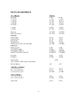
Страница 22: ...8SB Starting section with 4 100 mm offset AC 7SBO AC 8SBO FIRESTOPS Radiation shield ACRS ACRS Attic radiation shield AC RSA AC RSA Wall radiation shield 30 AC RSM30 ACRSM30 Insulated wall radiation shield 30 AC RSMI30 AC RSMI30 Roof brace AC BS AC BS Wall band AC BM AC BM Outside air kit ACZI Flex insulation outside register and coupling Flat roof flashing ACF ACF Adjustable roof flashing 1 12 7 ...

Страница 23: ...rs 42 SDB42 Brass louvers 36 TLB36 Brass louvers 42 TLB42 REPLACEMENT PARTS SE36 Refractory side PR SR2135 Refractory back PR SR2134 Refractory bottom PR SR124 Refractory front PR SR114 Fire grate PR SR2129 Rigid firescreen right PR SR2137D Rigid firescreen left PR SR2137G Folding door right PR SR2162D Folding door left PR SR2162G REPLACEMENT PARTS SB36 Refractory side PR SB141 Refractory back PR ...

Страница 24: ...20 DECORATIVE TRIMS AND PANELS FOR SE36 AND SR42 FIREPLACES DECORATIVE TRIMS FOR SB36 AND SB42 FIREPLACES TAB TAB TAB TAB TAB TAB TAB TAB TAB TAB TAB TAB TAB TAB TAB TAB ...

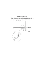
Страница 25: ...21 FIREPLACE MODEL SE36 INSTALLATION INSTRUCTIONS FOR THE DOOR HANDLE 2 1 4 ...

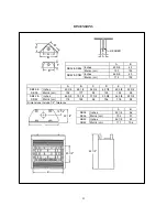
Страница 26: ... 8 69 1 2 34 3 4 49 1 8 40 3 8 22 3 4 SB36 SE36 Metric cm 102 177 88 125 102 58 Inches 46 3 8 75 1 2 37 3 4 53 3 8 46 3 8 22 3 4 SB42 SR42 Metric cm 118 192 96 136 118 58 Dimensions include 1 4 tolerance A B Inches 40 1 8 36 SB36 SE36 Metric cm 102 91 Inches 46 1 8 42 SB42 SR42 Metric cm 117 106 E F B A 12 1 4 20 1 2 B 42 1 2 HEADER 22 1 2 ...

Отзывы: