


CCOMe-965
CCOMe-965 - Rev. First Edition: 1.0 - Last Edition: 3.0 - Author: S.B. - Reviewed by G.G. Copyright © 2016 SECO S.r.l.
43
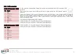
3.3.14
DisplayPort / HDMI Connectors
According to COM Express specifications Rel.2.1, Type 6 pinout defines three Digital
Display interfaces (DDI), that can be used to carry out DisplayPort and TMDS (HDMI/DVI)
interface.
Two of these Digital Display Interfaces (DDI#1 and DDI#2) are carried
out on two DP+HDMI combo connector, CN22 and CN23, type
FREEPORT p/n 62EHDS-30AN0-P1-D, with the pinout shown in the
tables on the left (it is HDMI and Display Port standard pinout).
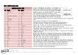
The signals reported on the table on the left don
’
t come directly from
the COM Express module; they are opportunely switched by a
dedicated IC, Texas Instruments SN75DP122A DisplayPort 1:2
Switch with Integrated TMDS Translator.
Switching between the two interfaces is automatic when an external display is connected to
one of the two connectors. Please consider that only one at a time of these two interfaces
can work, it is not possible to use the DP and HDMI interfaces of the same connector
simultaneously. In case both connectors are used, then TMDS interface (HDMI/DVI) takes the
priority.
The Display Port connection is, effectively, a multimode Display Port (DP++): this means that it
is also possible to connect HDMI displays to that connector by using a DP-to-HDMI adapter.
In the case that HDMI (TMDS) interface is used, it is necessary to set properly jumper JP4, in
order to specify if the connector is used for real HDMI connection or for use of DVI Displays
through a dongle.
Multimode DP + HDMI Combo Connector #1 - CN22
Display Port Section
Pin Signal
Pin Signal
1
DP
2
GND
3
DP1_LANE0-
4
DP
5
GND
6
DP1_LANE1-
7
DP
8
GND
9
DP1_LANE2-
10
DP
11
GND
12
DP1_LANE3-
13
DP1_CableAdapterDetect
14
GND
15
16
GND
17
DP1_AUX-
18
DP1_HPD
19
GND
20
+3.3V_DP1
HDMI Section
Pin
Signal
Pin
Signal
1
TMDS
2
GND
3
TMDS1_LANE2-
4
TMDS
5
GND
6
TMDS1_LANE1-
7
TMDS
8
GND
9
TMDS1_LANE0-
10
TM
11
GND
12
TMDS1_CLK-
13
---
14
---
15
TMDS1_I2C_CLK
16
TMDS1_I2C_DAT
17
GND
18
+5V_HDMI1
19
TMDS1_HPD
JP4 position
TMDS1 Connected to
1-2
HDMI display
2-3
DVI dongle


