SECO-LARM Electromagnetic Gate Locks with Face or Surface Mounting
SECO-LARM U.S.A., Inc
7
3.
Mount the armature plate. Once the
electromagnet is mounted, determine the
correct position of the armature plate. Use the
appropriate L bracket or Z bracket to position
the armature plate so that it will lay against the
electromagnet when activated. However, leave
a slight gap between the two so that the
armature plate does not slam against the
electromagnet when the gate is closed.
a.
Place the steel and rubber washers
over the armature screw between the
armature and the bracket (see page 3,
Overview). This will allow the armature
to pivot slightly around the armature
screw to compensate for gate
misalignment.
b.
Make sure the guide pins are inserted
loosely into guide holes to prevent the
armature from spinning.
c.
Tighten the sexnut enough so the armature can withstand the force of someone
attempting to pry the gate open while the electromagnet is engaged.
d.
Do not tighten the armature against the bracket. The armature must be able to pivot
slightly around the armature screw.
4.
Run the wires. Keep the wiring concealed.
a.
Run the wires into an out-of-sight location as close as possible to the electromagnet.
Run them inside hollow posts if possible.
b.
Use standard armored cable to prevent the wires from being cut between the
electromagnet and the out-of-sight location.
c.
The conduit fitting on the end is
3
/
4
” outside and
1
/
2
” on the inside. Use the appropriate
fitting if using conduit.
5.
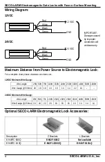
Connect the wires and test the unit. See Wiring Diagram on pg. 4 for more information.
6.
Insert the tamper caps into the mounting screw access holes of the electromagnet.
NOTE: This should be the last step, as once the tamper caps are in place, they are difficult to
remove.
Installation,
continued
:
Armature plate
Z Bracket
Armature plate
L Bracket


