background image

Operating instructions HLE 500/5000


14 

MAN_HLE500_HLE5000_eng_02 


100 

200 

150 

50 

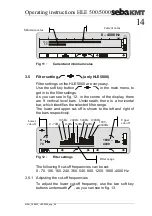
0 – 4000 Hz 


Fig 11 : 

Current and minimum value 


3.5 

Filter setting 

 (only HLE5000) 

Filter settings on the HLE 5000 are very easy.  
Use the soft key button 

 in the main menu, to 

get in to the filter settings.  
As  you  can  see  in  fig.  12,  in  the  centre  of  the  display,  there 
are  9  vertical  level  bars.  Underneath,  there  is  a  horizontal 
bar, which identifies the selected filter range. 
The  lower  and  upper  cut-off  is  shown  to  the  left  and  right  of 
the bars respectively.  


1800 – 
4000 

0 – 
70 


Fig 12 : 

Filter settings 

 
The following 9 cut-off frequencies can be set: 
0 - 70, 106, 160, 240, 360, 540, 800, 1200, 1800 -4000 Hz 

3.5.1  Adjusting the cut-off frequencies 

To  adjust  the  lower  cut-off  frequency,  use  the  two  soft  key 
buttons underneath 

, as you can see in fig. 13. 


Current value 

Minimum value 

Upper 
cut-off 

Lower 

cut-off 

0 - 70Hz 

106Hz 

160Hz 

240Hz 

360Hz 

540Hz 

800Hz 

1800 -
4000Hz 

1200Hz 

Filter range 

Содержание Hydrolux HLE 500

Страница 1: ...Prospekten ohne Rahmen Ansprechpartner Frau Badziura Leitungsortung Line Locating Rohrleitungsnetze Water Networks Kommunikationsnetze Communication Networks Elektrizit tsnetze Power Networks Edition...

Страница 2: ...Operating instructions HLE 500 5000 II MAN_HLE500_HLE5000_eng_02...

Страница 3: ...uality standard DIN ISO 9001 and the European standard EN 29001 This quality system was approved by the German Association for the Certification of Quality Systems with the numbers EN 19677 and DQS 19...

Страница 4: ...Operating instructions HLE 500 5000 IV MAN_HLE500_HLE5000_eng_02...

Страница 5: ...1 Headphones and microphone connection 11 3 2 Switching on 11 3 3 Volume and amplification 12 3 3 1 Setting the volume 12 3 3 2 Setting the gain 13 3 4 The amplification display 13 3 5 Filter setting...

Страница 6: ...with magnet 9 Fig 6 PAM U with 3 point foot 10 Fig 7 Start image with version number 11 Fig 8 Opening menu after switch on 12 Fig 9 Setting the volume 12 Fig 10 Setting the gain 13 Fig 11 Current and...

Страница 7: ...the ground microphone a new minimum display results A comparison of the measured values is thus always possible In the HISTOGRAM function each measurement location is stored one by one This equipment...

Страница 8: ...sides of the equipment and can be quickly plugged in or removed 1 3 Technical data Analysis bandwidth 0 Hz 4000 Hz Filter cut off frequencies 0 70 Hz 106 Hz 160 Hz 240 Hz 360 Hz 540 Hz 800 Hz 1200 Hz...

Страница 9: ...le to PAM W 1 VK65 3 point foot adapter PAM W 1D Carrying pole for PAM W 1 Universal PAM U microphone PAM U Magnetic adapter Sensor rod 3 point foot for PAM U PAM U D Extension rod VST T 1 Ground micr...

Страница 10: ...Optional accessories Radio module for wireless transmission between microphone and amplifier PAM 868 Sensor rod extension VST T 1 Special headphones highly insulated from extraneous noise KM2 Sliding...

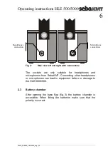
Страница 11: ...controls the devices which can be connected and the power supply 2 1 HLE 5000 500 controls Fig 1 HLE 5000 500 control panel 2 2 Connections at the side The sockets for the microphone and the headphone...

Страница 12: ...or headphones and microphones from SebaKMT Connecting other headphones or microphones can lead to equipment failure or damage to the HLE 5000 500 2 3 Battery chamber After opening the base flap fig 3...

Страница 13: ...hange the batteries change all 10 batteries at one time 2 5 Illumination of the LCD display By briefly pushing the on off button when the equipment is turned on the illumination for the display will b...

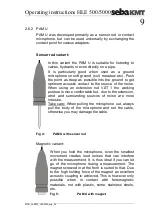
Страница 14: ...ly well shielded from the wind using a bell shaped guard The carrying pole can be removed with a quarter turn to the left This is particularly useful in reducing extraneous noise to a minimum when the...

Страница 15: ...the working posture is more comfortable but due to the extension wind and surrounding sources of noise are more intrusive Take care When pulling the microphone out always pull the body of the microph...

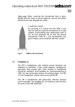
Страница 16: ...round microphone PAM W 1 but nevertheless very good results can be achieved with this variant Fig 6 PAM U with 3 point foot 2 7 Headphones The KR 2 headphones with ambient sound insulation are supplie...

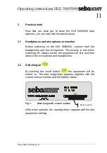
Страница 17: ...both the headphones and the microphone The reverse is true when switching off Always switch the equipment off first and then remove the microphone and headphones 3 2 Switching on By pushing the on of...

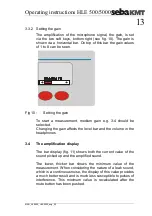
Страница 18: ...ped with separate controls for volume and amplification Thus every user can make the best settings for their personal characteristics 3 3 1 Setting the volume Using the two buttons on the right see fi...

Страница 19: ...g 3 4 should be selected Changing the gain affects the level bar and the volume in the headphones 3 4 The amplification display The bar display fig 11 shows both the current value of the sound picked...

Страница 20: ...erneath there is a horizontal bar which identifies the selected filter range The lower and upper cut off is shown to the left and right of the bars respectively 1800 4000 0 70 Fig 12 Filter settings T...

Страница 21: ...t off frequencies you can set the 9 frequencies specified above and can thus easily set the special filter range for every measurement After the filter range has been correctly set use the soft key bu...

Страница 22: ...should first of all push the mute button X see fig 1 This causes the sound in the headphones to be interrupted and the current level will be frozen This means that your hearing is protected as the lou...

Страница 23: ...value which is of particular significance when looking for burst pipes Fig 15 Dual segment analysis DSA With the first push of the mute button X the current measurement is stored and simultaneously d...

Страница 24: ...ording the flow noise of a valve To do that the microphone is put onto the pipe and the long term measurement is started Then you close the valve for a certain time at least 2 minutes and then open it...

Страница 25: ...he PWG The horizontal level bars respond particularly sensitively to impulses the bar is shown much larger and is delayed more and the filters are set to lower frequencies Of course if required the fi...

Страница 26: ...nd check the polarity of the batteries See fig 3 If the polarity of all of the batteries is OK the state of every single battery must be checked 4 3 No sound can be heard With working equipment there...

Страница 27: ......

Отзывы: