background image

24

KEY    PART            
NO.     NO.                DESCRIPTION

29

29

1

11

11

12

12

13

14

14

24

23

26

27

11

12

16

11

12

25

33

32

16

3

4

7

8

9

5

23

23

28

24

18

6

5

5

12

11

10

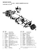
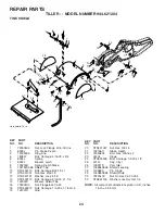
tine_shield_14_in

22

21

20

19

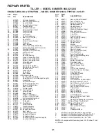
KEY    PART            
NO.     NO.                DESCRIPTION

1         73900500       Nut, Lock Flange  5/16-18 Unc
3         8393J             Pin, Stake, Depth
4         12000035       Ring, Klip
5         180847           Bolt, Carriage  5/16-18 x 3/4
6         8394J             Spring
7         8392J             Bracket, Latch
8         109230X        Spring, Depth Stake
9         102152X558  Shield, Tine
10       STD533110   Bolt, Carriage 5/16-18 x 1
11       STD541031   Nut, Hex  5/16-18
12       STD551131   Washer, Lock  5/16
13       STD533112   Bolt, Carriage  5/16-18 x 1-1/4
14       124343X        Bracket, Shield Tine
16       73900400       Nut, Flangelock 1/4-20
18       STD532512   Bolt, Carriage  1/4-20 x 1-1/4 Gr. 5
19       102701X        Grip

20       STD541037   Nut, Hex  3/8-16
21       102156X        Stake, Depth
22       74930632       Bolt, Hex  3/8-16 x 2
23       4440J             Hinge
24       STD532505   Bolt, Carriage  1/4-20 x 1/2
25       6712J             Cap, Vinyl
26       109227X        Pad, Idler
27       102686X558  Shield, Leveling
28       120588X        Pin, Hinge
29       104085X558  Shield, Side
32       73220400       Nut Fin Hex 1/4-20 Unc
33       STD551125   Washer Lock Hvy Hel 1/4

NOTE:

  All component dimensions given in U.S. inches.

 1 inch = 25.4 mm

REPAIR PARTS

TILLER - - MODEL NUMBER 944.621204

TINE SHIELD

Содержание CRAFTSMAN 944.621204

Страница 1: ...uctions Before Operating This Equipment MODEL NO 944 621204 OWNER S MANUAL Assembly Operation Maintenance Service and Adjustments Repair Parts 5 5 HP 14 INCH TINE WIDTH REAR TINE TILLER WITH COUNTER ROTATING TINES Sears Canada Inc Toronto Ontario M5B 2B8 ...

Страница 2: ... the controls and the proper use of the equipment Know how to stop the unit and disengage the controls quickly Never allow children to operate the equipment Never allow adults to operate the equipment without proper instruction Keep the area of operation clear of all persons par ticularly small children and pets PREPARATION Thoroughly inspect the area where the equipment is to be used and remove a...

Страница 3: ...E REPAIR PARTS SECTION OF THIS MANUAL FOR PART NUMBER SAFETY RULES 2 CUSTOMER RESPONSIBILITIES 3 PRODUCT SPECIFICATIONS 3 WARRANTY 3 ASSEMBLY 4 6 OPERATION 7 10 MAINTENANCE SCHEDULE 11 TABLE OF CONTENTS MAINTENANCE SCHEDULE 11 13 SERVICE ADJUSTMENTS 14 17 STORAGE 18 TROUBLESHOOTING 19 REPAIR PARTS TILLER 20 26 REPAIR PARTS ENGINE 27 32 SERVICE PARTS ORDERING BACK COVER LIMITED ONE 1 YEAR WARRANTY ...

Страница 4: ...ting position standing behind tiller handles Your new tiller has been assembled at the factory with exception of those parts left unassembled for shipping purposes To ensure safe and proper operation of your tiller all parts and hardware you assemble must be tightened securely Use the correct tools as necessary to insure proper tightness 1 Carriage Bolt 3 8 16 UNC x 1 Gr 5 1 Center Locknut 3 8 16 ...

Страница 5: ...CK HANDLE ASSEMBLY UP POSITION FIG 4 UNPACKING CARTON See Fig 2 CAUTION Becarefulofexposedstaples when handling or disposing of carton ing material IMPORTANT WHEN UNPACKING AND ASSEMBLING TILLER BE CAREFUL NOT TO STRETCH OR KINK CABLES While holding handle assembly cut cable ties securing handle assembly to top frame Let handle assembly rest on tiller Remove top frame of carton Slowly ease handle ...

Страница 6: ...LLER FROM CRATE Adjust handle assemby to lowest position Be sure lock lever is tightened securely Makesureshiftleverindicatorisin N neutral position See Fig 7 Tilt tiller forward by lifting handle Separate cardboard cover from leveling shield Rotate tiller handle to the right and pull tiller out of carton CHECK TIRE PRESSURE The tires on your unit were overinflated at the factory for shipping purp...

Страница 7: ... or in literature supplied with the product Learn and understand their meaning SHIFT LEVER DEPTH STAKE LEVELING SHIELD OUTER SIDE SHIELD DRIVE CONTROL BAR THROTTLE CONTROL DEPTH STAKE Controls depth at which tiller will dig DRIVE CONTROL BAR Used to engage tines LEVELING SHIELD Levels tilled soil OUTER SIDE SHIELD Adjustable to protect small plants from being buried RECOIL STARTER HANDLE SHIFT LEV...

Страница 8: ...ND TILLER Release the drive control bar Move throttle control to SLOW position Move shift lever indicator to R reverse position Hold drive control bar against the handle to start tiller movement HARD TO SHIFT GEARS Brieflyengagedrivecontrolbarandreleaseorrocktiller forward and backward until are able to shift gears FIG 9 DRIVE CONTROL BAR DISENGAGED POSITION THROTTLE CONTROL TRANSPORT POSITION DEE...

Страница 9: ... already filled with SAE 30 summer weight oil With engine level clean area around oil filler plug and remove plug Engineoilshouldbetopointofoverflowingwhenengine is level For approximate capacity see PRODUCT SPECIFICATIONS on page 3 of this manual All oil must meet A P I Service Classification SF SJ Reinstall engine oil cap and tighten For cold weather operation you should change oil for easier st...

Страница 10: ...hields to protect small plants from being buried Cultivate up and down the rows at a speed which will allow tines to uproot weeds and leave the ground in rough condition promoting no further growth of weeds and grass See Fig 15 FIG 15 FIG 13 TINE SHEAR PINS The tine assemblies on your tiller are secured to the tine shaft with shear pins See TINE REPLACEMENT in the Service and Adjustments section o...

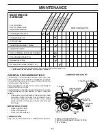
Страница 11: ...abuseornegligence Toreceive fullvaluefromthewarranty theoperatormustmaintaintiller as instructed in this manual Some adjustments will need to be made periodically to properly maintain your tiller All adjustments in the Service and Adjustments section of this manual should be checked at least once each season Once a year you should replace the spark plug clean or replace air filter and check tines ...

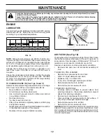
Страница 12: ...Change the oil after every 50 hours of operation or at least once a year if the tiller is not used for 50 hours in one year Check the crankcase oil level before starting the engine and after each five 5 hours of continuous use Add SAE 30 motor oil or equivalent Tighten oil filler plug securely each time you check the oil level TEMPERATURE RANGE ANTICIPATED BEFORE NEXT OIL CHANGE SAE VISCOSITY GRAD...

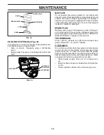
Страница 13: ...ction Replace if damaged SPARK PLUG Replace spark plugs at the beginning of each tilling sea son or after every 50 hours of use whichever comes first Spark plug type and gap setting are shown in PRODUCT SPECIFICATIONS on page 3 of this manual TRANSMISSION Once a season lubricate the right hand side gear case grease fitting with 1 oz of EP 1 Grease CLEANING Do not clean your tiller when the engine ...

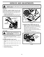
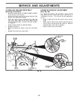
Страница 14: ... free of gasoline or oil which can damage rubber TO REMOVE WHEEL See Fig 21 Place blocks under transmission to keep tiller from tipping Remove outer side shield by removing nuts A and B Remove inner side shield by removing nuts C and D Remove hairpin clip and clevis pin from wheel Remove wheel and tire Repair tire and reassemble tire_4 NUT B NUT A INNER SIDE SHIELD OUTER SIDE SHIELD NUT D NUT C HA...

Страница 15: ...IN GROOVE ON TOP OF IDLER PULLEY NOTE POSITION OF BELT TO GUIDES Check belt adjustment as described below Replace belt guard Reposition wheel and replace clevis pin and hairpin clip Replace inner and outer side shields GROUND DRIVE BELT ADJUSTMENT See Fig 23 For proper belt tension the extension spring should have about 5 8 inch stretch when drive control bar is in ENGAGED position This tension ca...

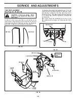
Страница 16: ... assembled as shown in Fig X3 Sharpened tine edges will rotate rearward from above TRANSMISSION TINE TINE 3 1 2 MAX tine_12 SHARP EDGE HAIRPIN CLIP SHARP EDGES SHARP EDGE SHARP EDGE SHARP EDGE COUNTER TINE ROTATION TINE REPLACEMENT See Figs 24 25 and 26 CAUTION Tines are sharp Wear gloves or other protection when han dling tines A badly worn tine causes your tiller to work harder and dig more shal...

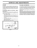
Страница 17: ...tment procedure Loosen cable clamp screw Move throttle lever up until it touches high speed stop and hold in this position Tighten cable clamp screw securely TO ADJUST CARBURETOR The carburetor has a high speed jet and has been preset at the factory and adjustment should not be necessary However minoradjustmentsmayberequiredtocompensate for differences in fuel temperature altitude or load If the c...

Страница 18: ... Inspect and replace belts if necessary See belt re placement instructions in the Service and Adjustments section of this manual Lubricate as shown in the Maintenance section of this manual Be sure that all nuts bolts and screws are securely fastened Inspect moving parts for damage breakage and wear Replace if necessary Touch up all rusted or chipped paint surfaces sand lightly before painting ENG...

Страница 19: ...fuel 6 Drain fuel tank and refill with fresh gasoline 7 Water in fuel 7 Drain fuel tank and carburetor and refill tank with fresh gasoline 8 Clogged fuel tank 8 Remove fuel tank and clean 9 Spark plug wire loose 9 Connect and tighten spark plug wire 10 Dirty engine air screen 10 Clean engine air screen 11 Dirty clogged muffler 11 Clean replace muffler 12 Carburetor out of adjustment 12 Make necess...

Страница 20: ...900400 Nut Lock 1 4 20 30 7192J Tie Cable 31 150696 Bolt Pivot 1 180634 Throttle Control 2 141406 Grip Handle 3 110673X Grommet Handle 4 127254X Bar Drive Control Assembly 5 6712J Cap Vinyl 6 188403X018 Panel Control 7 110641X Bushing Split 8 17720408 Screw Thd Cut 1 4 20 x 1 2 9 72010520 Bolt 5 16 18 unc x 2 1 2 10 110646X Handle Grip 11 STD624003 Clip Hairpin 12 81328 Bolt Shoulder 13 187497 Han...

Страница 21: ...312 Washer 13 32 x 13 16 x 12 Ga NOTE All component dimensions given in U S inches 1 inch 25 4 mm 1 STD541431 Nut Keps 5 16 18 2 STD551137 Washer Lock 3 8 3 STD541037 Nut Hex 3 8 16 4 170127 Shield Inner Belt Guard 5 164329 Pin Spirol Flared 6 110111X Lever Shift 7 STD532505 Bolt Carriage 1 4 20 x 1 2 Gr 5 8 8700J Plate Shift Indicator 9 86777 Screw Hex Washer Head Slotted 10 24 x 1 2 10 9484R Cli...

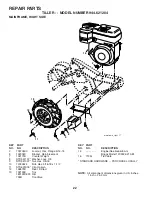
Страница 22: ...2332X Bracket Reinforcement 7 102173X Counter Weight 8 STD551137 Washer Lock 3 8 9 STD541037 Nut Hex 3 8 16 10 74760524 Bolt Hex 5 16 18 x 1 1 2 11 STD624003 Clip Hairpin 12 126875X Rivet Drilled 13 102190X Tire 183122X624 Rim 795R Tire Valve 15 Engine See breakdown Briggs Model 120302 0213 E1 16 7192J Tie Cable STANDARD HARDWARE PURCHASE LOCALLY NOTE All component dimensions given in U S inches 1...

Страница 23: ...1 2 52 STD541031 Nut Hex 5 16 18 53 165140 Kit Bearing 58 179520 Bolt Shoulder 60 183226 Fitting Grease 6066J Grease Plastilube 1 NOTE All component dimensions given in U S inches 1 inch 25 4 mm KEY PART NO NO DESCRIPTION 1 188554 Transmission Assembly Includes Key Nos 2 52 2 188482 Gearcase L H w Bearing In cludes Key No 4 3 161963 Gasket Gearcase 4 5020J Bearing Needle 5 1370H Washer Thrust 5 8 ...

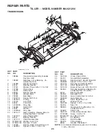
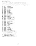
Страница 24: ...ut Hex 5 16 18 12 STD551131 Washer Lock 5 16 13 STD533112 Bolt Carriage 5 16 18 x 1 1 4 14 124343X Bracket Shield Tine 16 73900400 Nut Flangelock 1 4 20 18 STD532512 Bolt Carriage 1 4 20 x 1 1 4 Gr 5 19 102701X Grip 20 STD541037 Nut Hex 3 8 16 21 102156X Stake Depth 22 74930632 Bolt Hex 3 8 16 x 2 23 4440J Hinge 24 STD532505 Bolt Carriage 1 4 20 x 1 2 25 6712J Cap Vinyl 26 109227X Pad Idler 27 102...

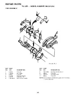
Страница 25: ...3 8 24 4 4 2 1 1 5 3 3 11 11 10 9 9 6 7 8 2 tine_ipb_99_2 NOTE All component dimensions given in U S inches 1 inch 25 4 mm KEY PART NO NO DESCRIPTION KEY PART NO NO DESCRIPTION 8 74610616 Bolt Hex Hd 3 8 24 x 1 9 4460J Tine RH 10 132722 Hub Asm RH 11 6555J Tine RH REPAIR PARTS TILLER MODEL NUMBER 944 621204 TINE ASSEMBLY ...

Страница 26: ...cement 7 102180X Decal Shift Indicator 8 157984 Decal Cout Rot Tines 9 120076X Decal Warning Rotating Tines 10 168260 Decal Tine Depth Stake 11 162384 Decal Warning Tine Shield 12 166138 Decal Engine 13 167156 Decal Engine 191820 Manual Owner s English 191821 Manual Owner s French 9 5 13 11 2 7 REPAIR PARTS TILLER MODEL NUMBER 944 621204 DECALS 1 3 10 ...

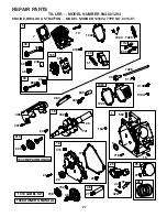
Страница 27: ... NO 0213 E1 20 22 12 21 306 1058 OWNER S MANUAL 1019 LABEL KIT 15 1 307 415 3 718 552 18 7 1022 40 1034 1029 45 1026 13 337 635 5 914 383 868 993 619 1022 914A 40 35 238 33 34 1023 146 16 741 24 46 746 742 32 30 29 27 28 220 219 27 25 26 36 830 192 32A 155 122 51 15A 1330 REPAIR MANUAL 332 914B ...

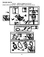
Страница 28: ...YPE NO 0213 E1 108 130 95 127 51 104 137 276 276 134 133 975 117 186 692 122 51 365 125 98 121 CARBURETOR OVERHAUL KIT 104 137 276 127 633A 633 134 137 633 977 CARBURETOR GASKET SET 51 633A 122 51 20 3 7 358 ENGINE GASKET SET 993 868 12 1022 163 633A 97 122 51 633 109 163 163 163 276 118 883 ...

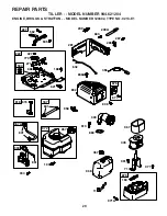
Страница 29: ...RIGGS STRATTON MODEL NUMBER 120302 TYPE NO 0213 E1 334 851 333 209 663 562 505 227 616 209A 632 836 836A 190 832 676 677 300 883 613 615 356 601 222 773 188 621 427 271 668 504 281 957 972 187 601 187A 971A 875 163 967 445 971 961 717 968 467 11 267 265 958 ...

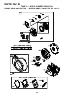
Страница 30: ... 944 621204 ENGINE BRIGGS STRATTON MODEL NUMBER 120302 TYPE NO 0213 E1 1022 7 1095 VALVE GASKET SET 51 868 993 332 23 363 455 1005 1070 1036 EMISSIONS LABEL 48 55 456 58 459 689 597 608 59 60 1210 1211 304 305 65 1329 REPLACEMENT ENGINE ...

Страница 31: ...17 Connector Hose 187 691050 Line Fuel Cut to Required Length 187A 692601 Line Fuel Molded KEY PART NO NO DESCRIPTION 188 699479 Screw Control Bracket 190 699220 Screw Fuel Tank 192 694543 Adjustor Rocker Arm 209 691278 Spring Governor 209A 692571 Spring Governor 219 693578 Gear Governor 220 691724 Washer Governor Gear 222 699589 Bracket Control 227 692573 Control Lever Governor 238 691300 Cap Val...

Страница 32: ...Air Cleaner Bracket 967 273356 Filter Pre Cleaner 968 693460 Cover Air Cleaner 971 699629 Screw Air Cleaner Base 971A 690349 Screw Air Cleaner Base 972 694260 Tank Fuel 975 493640 Bowl Float 977 697001 Set Carburetor Gasket 993 694088 Gasket Cylinder Head Plate 1005 692592 Fan Flywheel 1019 694852 Kit Label 1022 691890 Gasket Rocker Cover 1023 499924 Cover Rocker 1026 693517 Rod Push 1029 691230 A...

Страница 33: ...33 SERVICE NOTES ...

Страница 34: ...34 SERVICE NOTES ...

Страница 35: ...35 SERVICE NOTES ...

Страница 36: ...PRINTED IN THE U S A 191820 03 03 04 TR 02488 ...

Отзывы: