background image

Содержание Craftsman 390.250097

Страница 1: ...g Instructions Before FirstUse of This Product Save This Manual For Future Reference I RRFTSMRN 112 HP SHALLOW WELL WATER SYSTEM Safety Instructions Installation Electrical Maintenance Repair Parts Se...

Страница 2: ...ge To do so can boll water h_lde pump causing hazardous pressure in unit risk of explosion and possibly scalding persons handling pump _ CAUTION I Motor normally operates at high temperature and will...

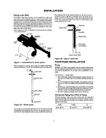
Страница 3: ...in more water Part of the water is diverted back to the jet where it passes through the nozzle and venturi This cremes more vacuum to draw in more water In shallow wells less than 20 feet deep the vac...

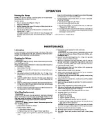
Страница 4: ...about 1 less lift for every 1 000 feet of elevation above sea level For ex ample at Denver Colorado Elev 5 000 the pump loses five feet of lift The maximum depth from which it would pump water would...

Страница 5: ...become steady air may be leaking into the system check for leaks in the piping on the suction side of the pump NOTICE To prevent watedogging check tank air charge annually To Check Tank Air Charge if...

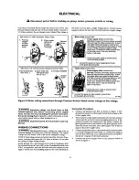
Страница 6: ...31870398 Figure 4 Motor wiring connections through Pressure Switch Match motor voltage to line voltage _ WARNING_ Hazardous voltage Can shock burn or kill Connect ground wire before connecting power s...

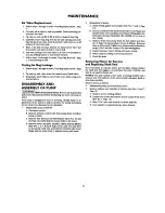
Страница 7: ...Bag Replacement _ WAFtNING Be sure LL air pz _su_ has _ 1 released from tank before removing nuts from flange Failure to do this may I_sult in serious or fatal injut_ Do not att_tnpt to open tank unle...

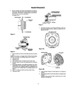
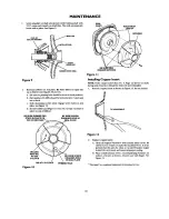
Страница 8: ...xnuts and lockwashers Key Nos 24 and 23 Page 12 which hold the pump body to the motor D Remove motor seal plate impeller rubber pad and diffuser Key Nos 1 3 7 g and 9 Palle 12 as a unit You may have t...

Страница 9: ...clean cloth B Wet outer edge of cup seal with petroleum jelly or detergent soludon C With finger pressure press firmly and squarely into cavity Polished face of seat faces inside of pump If seat will...

Страница 10: ...ER PAD STAYS IN PLACE ON BE SURE SCREW ENGAGES HOLE IN SEAL PLATE MOLDED PART NO AT 9 90 BE SURE SCREW O CLOCK ENGAGES HOLE IN SEAL PLATE RIB AT 6 O CLOCK Figure I 0 PRIMING HOLE BE SURE NIBS ENGAGE N...

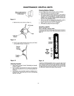
Страница 11: ...In some areas well water contains gases which must be allowed to escape before the water is used This can be done as shown in Figul_ 16 Gases rise to surface D Clean out any surplus Permatex from ins...

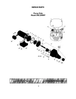
Страница 12: ...REPAIR PARTS Pump Only Model 390 250097 1A 1C 26 28 27 25 24 23 22 4 6 21 8 9 2O 10 18 17 I 14 11 13 AVC Port 12 J 12A 12B 12...

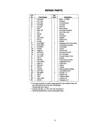
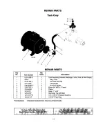
Страница 13: ...t66 5P 1 Check Valve 13t WC78 41T 1 Pipe Plug 1 8 NPT 14t Ut11 212T 1 90 Hose Barb 15 U37 670P 1 PressureSwitch Tube 16 J20 18 1 Gasket 17 N76 29P 1 Pump BodyJet Insert 18 U30 742SS 4 Cap screw 10 16...

Страница 14: ...t U19 55SS U74 37X U78 972P U78 107PTt WC78 41T 1 1 1 1 6 1 2 1 1 1 1 Tank Assembly Includes Diaphragm Valve Nuts Inlet Flange Bag Vinyl Air Valve with Cap Inlet Flange Nut 5 16 18 Hex Elbow 3 4 MPT x...

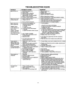
Страница 15: ...tor is wiredincorrectly 5 Water level in wellis lower than estimated 1 Pipes leak 2 Faucets or valves are open 3 Foot valve leaks 4 Pressureswitchis out of adjustment 5 Air chargetoo lowin Captive Air...

Страница 16: ...ement partsyouneed Call7 am 7 pm 7 daysaweek 1 800 366 PART 1 800 366 7278 Forin borne majorbrandrepairservice Call24 hoursa day 7 daysaweek 1 8OO 4 REPAIR 1 800 473 7247 Forthelocation of a Sears Rep...

Отзывы: