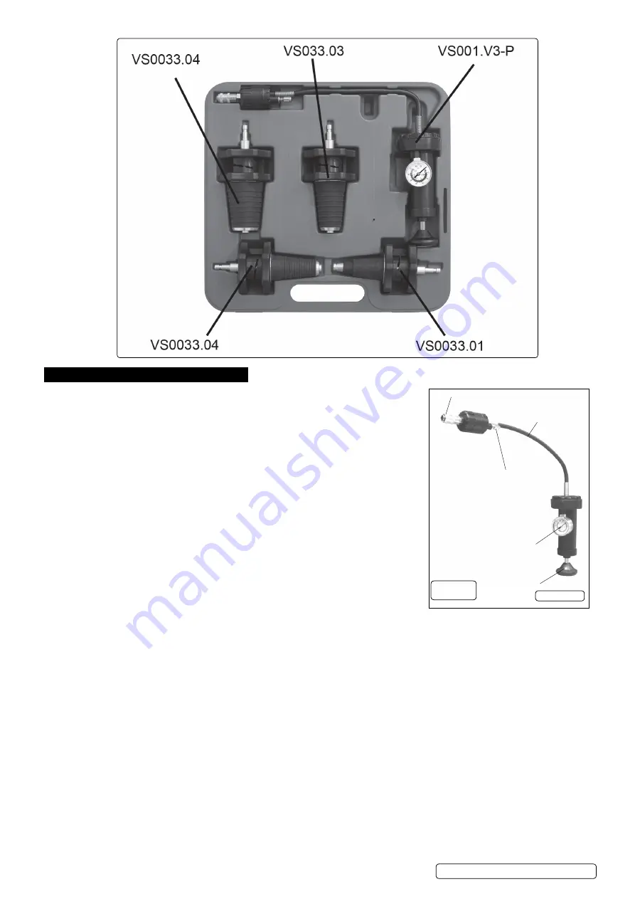
5. operation
5.1.
Follow the manufacturer’s instructions for removal of filler cap, use a thick cloth or gloves
and arm protection if the system is known to be hot and or under pressure.
5.2.
Select the correct adaptor by first measuring or gauging by eye the filler neck diameter.
5.3.
ensure the sealing conical nozzle is in its “relaxed” condition by visually inspecting the
hand wheel incremental cam lobes. The gap between handwheels will be at their closest.
5.4.
Insert the conical nozzle end of adaptor and ensure a partial seal.
5.5.
Adjust seal compression integrity by gripping the handwheel nearest the nozzle and
rotating the top handwheel clockwise until an adequate seal is obtained. Resistance will
increase with seal compression via the incremental cam lobes.
5.6.
Attach the quick coupler of the pump hose on to the conical adaptor (fig.1).
note!
due to the design of the internal pump seal, a vigorous pumping action is required to
activate the seal and pressurise the system. A light or slow pumping action will prove
ineffective. The larger the air space within the cooling system being tested, the
more vigorous the initial pumping should be. By filling the cooling system and therefore
reducing the airspace within, less effort will be needed to pressurise it.
5.7.
Pump the system until the pressure gauge indicates approximately 15 psi.
5.8.
If gauge pointer remains stationary for one minute it will indicate that the cooling system is
in good working order.
5.9.
If the pointer falls, it indicates that the system has a leak resulting in loss of pressure.
5.10.
Check the system for water leaks and, if located, repair accordingly.
5.11.
If there is pressure loss but no external water leakage check condition of the head gasket.
5.12.
Re-test to ensure the repaired system is in good working order.
5.13.
once the test is complete, release the air pressure by depressing the spring loaded pressure relief valve (fig.1).
5.14.
disconnect the quick coupler (fig.1).
5.15.
Remove the conical adaptor assembly by firstly gripping the handwheel nearest the nozzle and secondly relaxing the seal
compression by rotating the top handwheel counter clockwise fully up to mechanical stop.
Quick coupler
Pump plunger
Pressure relief valve
Pressure gauge 0-35psi (0-2.5bar)
VS001.V3-P
Flexible hose
fig.1
VS0033 Issue 2 (HF) 29/04/19
Original Language Version
© Jack Sealey limited


