


Original language version
INTRODUCTION:
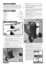
All our Supermig models are suitable for welding with CO²,
Argon or CO²/Argon mix. Each uses a forced air cooling system to slow
transformer heating in order to increase duty cycle and a non-live torch to
prevent the risk of accidentally striking an arc. All models are supplied with an
Argon/CO² regulator. Welders are illustrated with gas bottles to give an
indication of size only; gas is not included. A contract for the supply of gas
should be arranged with your local gas distributor or you can purchase
disposable bottles from your local Sealey dealer.
MODEL No. . . . . . . . . . . . . . . . . . . . . . . . . . . . . . . . . . . . . . . . . SUPERMIG140
Welding Current . . . . . . . . . . . . . . . . . . . . . . . . . . . . . . . . . . . . . . . . . . 30 - 140A
Wire Capacity . . . . . . . . . . . . . . . . . . . . . . . . . . . . . . . . . . . . . . . . . . 0.7 - 5.0kg
Duty Cycle . . . . . . . . . . . . . . . . . . . . . . . . . . . . . . . . . .50% @ 55A, 20% @ 80A
Cooling System . . . . . . . . . . . . . . . . . . . . . . . . . . . . . . . . . . . . . . . . . .Forced Air
Spot welding timer . . . . . . . . . . . . . . . . . . . . . . . . . . . . . . . . . . . . . . . . . . . . . NO
Gas Type . . . . . . . . . . . . . . . . . . . . . . . . . . . . . . . . . CO², Argon, CO²/Argon mix
Torch . . . . . . . . . . . . . . . . . . . . . . . . . . . . . . . . . . . . . . . . . . . . . . . . . . . Non-live
Power Input . . . . . . . . . . . . . . . . . . . . . . . . . . . . . . . . . . . . . . . . . . . . . 230V 1ph
Absorbed power. . . . . . . . . . . . . . . . . . . . . . . . . . . . . . . . . . . . . . . . . . . . . 2.8kW
Case size . . . . . . . . . . . . . . . . . . . . . . . . . . . . . . . . . . . . . . . . . . . . . . . .Compact
Weight . . . . . . . . . . . . . . . . . . . . . . . . . . . . . . . . . . . . . . . . . . . . . . . . . . . . . 22kg
4. ASSEMBLY & PREPARATION
4.1. Assembly.
4.1.1. HANDLE. Take the straight metal handle section and identify the end
which has a rectangular hole in it's rounded top surface. See 'C' in
fig.1-A.
4.1.2. Ensuring that this hole is uppermost, insert the handle into the
opening in the front of the plastic handle until the catch 'D' engages in
the hole 'C' as shown in fig.1-B.
4.1.3. WHEELS. Referring to fig.2, attach a wheel (1) to axle (2) using a circlip
(3) and insert a hub cap (4) into the centre of the wheel.
4.1.4. Raise the welder from the ground by approximately 70mm and insert
the axle fixing plates (5) through the slots in the rear platform as shown
below.
4.1.5. Slide the axle (2) underneath the rear platform and through the holes in
the axle fixing plates.
4.1.6. Slide the other wheel (1) over the protruding axle (2) and fix in place
using a circlip (3).
4.1.7. Push the other hub cap (4) into the centre of the wheel.
4.1.8. FOOT. Attach the bent metal foot to the underside of the welder just
back from the front panel using the two self tapping screws provided.
fig.1
fig.2
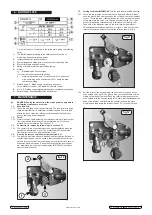
4.2. Mounting the gas cylinder. See fig.3. (See Section 4.3 regarding
gas types)
4.2.1. Attach the black gas cylinder belt (D) to the back of the welder by
passing it through the two pressed metal loops on the back panel. Place
the lower end of the cylinder (C) (Not supplied) into the metal hoop (E)
and fasten the belt around the cylinder.
4.3. Connecting the gas cylinder
4.3.1. Ensure that the regulator (B) is closed (knob turned fully clockwise)
and then screw it onto the cylinder (finger tight only). Once the regulator
has opened the cylinder valve, indicated by the sound of gas escaping,
screw it one full turn further, which is sufficient to seal the cylinder.
WARNING!
Excessive tightening of the regulator will over-compress the
sealing washer and allow the gas to leak.
4.3.2. Push the gas tube (A) into the regulator (to remove tube, press the
collet in and pull the tube out).
Leave the regulator closed until the welder is fully set up and you
are ready to weld
.
4.3.3. When you are ready to commence welding switch the machine on and
turn the regulator knob halfway for a flow of approx. 2l/min, and all the
way for a max. flow of approx. 4l/min.
4.3.4. Always remove the flow regulator after use if the machine is to be
stored for any length of time.
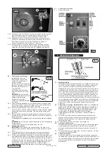
4.4. Fitting a reel of wire.
4.4.1. Open the side compartment on the welder by placing your finger into
the black catch and lifting both the catch and the door. The welder is
supplied with a mini spool of mild steel wire, but will accept spools of
up to 5kg without modification.
4.4.2. Referring to fig.4, rotate the pressure knob (F) anti-clockwise and
remove it from the threaded spindle together with the spring (E) and
the top disc (D). Small reels of wire will run on the spindle itself. The
larger 5kg wire reel will run on the larger diameter flange at the base of
the reel spindle (A). Place the wire reel (C) onto the spindle ensuring
that the wire withdraws from the top of the spool in a forwards direction
towards the wire feed unit. Place
the plastic top disc (D) over the
end of the spindle followed by
the reel spring (E). Thread the
pressure knob (F) onto the end
of the spindle and screw it down
clockwise until the spring is
partially compressed. The reel
take off pressure should be set to
provide a mild braking effect to
prevent overrun where loose
coils of wire form on the reel. Do
not overtighten this knob as too
much braking will conflict with the
wire tension set on the wire drive
unit.
fig.3
fig.4
2. INTRODUCTION
3. SPECIFICATION
© Jack Sealey Limited
SUPERMIG140 Issue No:2(L) 05/08/14