


7.3.
Turning feed roller
IMPORTANT:
Turn the feed roller to suit the wire size.
There are two grooves on the feed roller, 0.6mm and 0.8mm. Always have the groove that is being
used on the outside of the roller (nearest to you). To turn the feed roller first loosen the wire tension
knob and move it into its down position (see fig.9-1) then move the tensioning roller assembly to its up
position (see fig.9-2). Take hold of the triangular knob on the roller retainer and rotate it 90°anti-clock
wise to release it as shown in fig.9.3. Now pull the roller retainer off the drive spindle to reveal the roller
as shown in fig.10. Pull the roller off the drive spindle, flip it over and put it back on the drive spindle.
(See fig 11) The groove size you require should now be visible on the face of the roller. Push the roller
retainer back onto the drive spindle with the opening facing left. Ensure that the flanges at the base of
the retainer, seat fully into the circular recess in the main moulding and then rotate the retainer through
90° to lock it in place.
7.4.
Contact tip
(to remove tip follow steps in 4.3).
The contact tip is a consumable item and must be
replaced when the bore becomes enlarged or oval. The contact tip MUST be kept free from spatter to
ensure an unimpeded flow of gas.
7.5.
Gas cup
(to remove cup follow steps in 4.3).
The gas cup must also be kept clean and free from
spatter. Build-up of spatter inside the gas cup can cause a short circuit at the contact tip which will
result in either the fuse blowing on the printed circuit card, or expensive machine repairs. To keep the
contact tip free from spatter, we recommend the use of an anti-spatter spray.
7.6.
Replacing wire liner.
A worn or damaged wire liner will seriously affect the performance of the welder
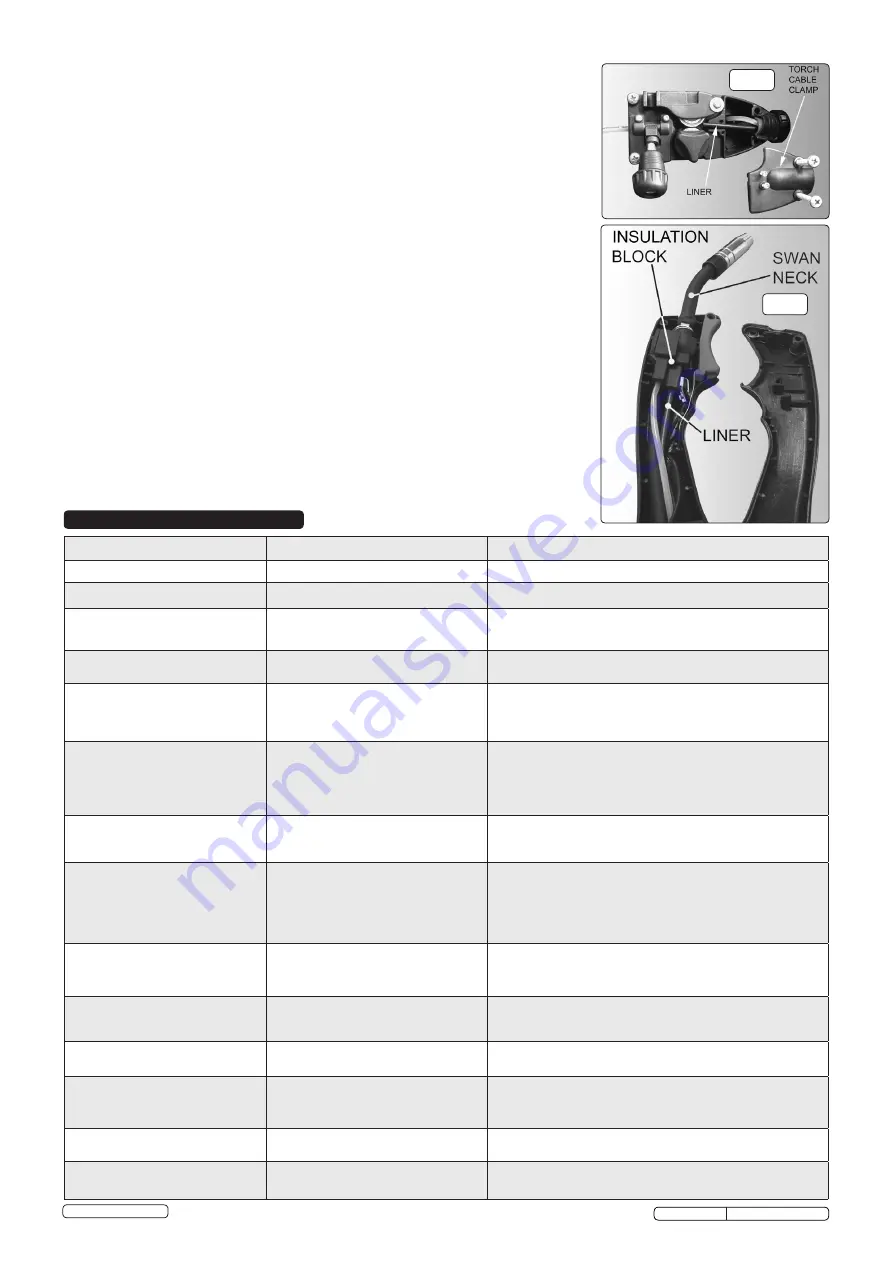
and should be immediately replaced. First wind the wire back onto the spool and secure it. Remove the
four screws securing the torch cable clamp to the wire feed unit (fig.12) and take off the clamp. Undo
the torch case (fig.13) and pull the wire liner from insulation block. Pull out the liner from the torch
cable and insert the new one. Reverse the process to re-assemble. Ensure the liner is fully inserted
into the torch insulation block and reassemble the torch. Trim the other end of the liner as close to the
feed roller as possible. Replace the torch cable clamp.
7.7.
Replacing gears.
An inexperienced welder can allow spatter to build up in the tip and shroud. In severe
cases this can block the wire feed causing gear damage in the wire drive. To check if the gears are
worn depress the button on the torch with the set switched on. If the gears are worn, a grating sound
will be heard coming from the wire feed motor and you may also observe the feed roller vibrating
instead of rotating smoothly. In this case, open the gearbox, remove the worn or damaged gears and
replace with new ones.
fig.13
fig.12
PROBLEM
POSSIBLE CAUSE
REMEDY
Weld current interrupted
Overheating protection activated due to overload
Protection automatically resets when transformer has cooled (approx. 15 min).
No weld current, fuse blowing in 13amp plug
Rectifier blown
Replace rectifier.
No weld current
Bad connection between clamp and workpiece
Break in earth lead
Break in torch lead
Clean or grind contact surface and weld area.
Repair or replace earth lead.
Repair or replace.
Feed motor not working
Gear damaged or worn
Motor defective
Replace gears (Section 7).
Replace motor (Contact service agent).
Wire does not feed, feed roller rotates
Pressure roller improperly adjusted
Dirt, copper, dust, etc. have collected in torch liner
Gas cup (nozzle) or tip defective
Deformed wire
Adjust tension.
Clean the liner from the machine forward. Use compressed air. If too much dirt,
replace the liner (Section 7).
Replace gas cup (nozzle) and/or tip (Section 7). Check roller tension (Section 4).
Wire feeds unevenly
Dirt, etc, in liner
Gas cup (nozzle) or tip defective
Gas cup (nozzle) spattered
Feed roller groove clogged
Feed roller groove deformed
Pressure roller tension incorrect
Clean the liner from the machine forward using compressed air.
Replace gas cup (nozzle) and/or tip (Section 7).
Clean or replace gas cup (nozzle) (Section 7).
Clean feed roller (Section 7).
Replace feed roller (Section 7).
Adjust tension (Section 4).
Unstable arc
Incorrect settings
Impurities in weld area
Worn or defective gas cup (nozzle)
Check settings (Section 5).
Clean and/or grind workpiece (Section 5).
Replace gas cup (nozzle) (Section 7).
Porous weld
No gas
Gas cup clogged
Draft blowing away shielding gas
Rusty/dirty joints
Torch too far from, or at wrong angle to, workpiece
Gas leak
Open gas cylinder, regulate gas flow.
Clean or replace cup (Section 7).
Screen off welding site or increase gas flow.
Clean or grind the workpiece (Section 5).
Gas cup to workpiece should be 8-10mm. Torch angle approx 75º.
Check hoses, connections and torch assembly (Section 7).
Wire sticking in gas cup (nozzle)
Worn or defective gas cup (nozzle)
Wire deformed
Wire speed too slow
Replace gas cup (nozzle) (Section 7).
Check roller tension (Section 4).
Increase wire speed.
Irregulars weld bead
Torch incorrectly held
Wire weaving in weld pool
Use correct torch angle.
Check roller tension and adjust (Section 4).
Weld bead too narrow and raised
Weld current too low
Weld speed too fast
Increase power and wire speed (Section 5).
Move torch slower and weave a little more.
Weld bead too wide
Weld current too high
Weld speed too slow
Arc too long
Decrease current and wire speed (Section 5).
Move torch faster and weave less.
Bring torch closer to workpiece.
Poor penetration
Weld current too low
Arc too long
Increase current and wire speed (Section 5).
Bring torch closer to workpiece.
Excessive penetration
Weld current too high
Weld speed too slow
Incorrect distance of torch to workpiece
Decrease current and wire speed (Section 5).
Move torch faster.
Torch distance should be 8-10mm.
SUPERMIG130 Issue No:2(L) 26/08/14
Original Language Version
© Jack Sealey Limited
8. TROUBLESHOOTING


