


s
Duty Cycle
u
Rated weld current
u
Conventional load voltage
u
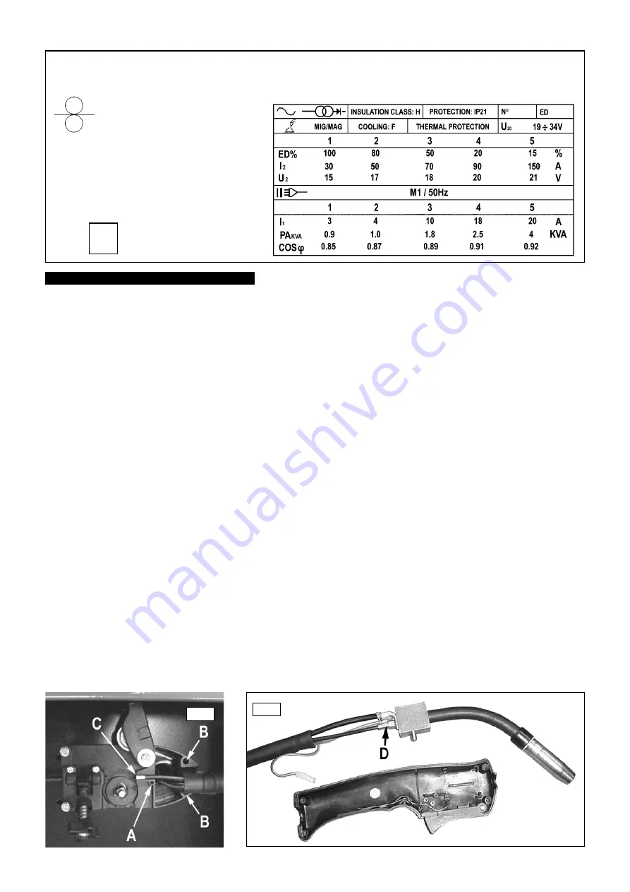
GUIDE TO RATINGS PLATE AND SYMBOLS
( For actual ratings of your model refer to front panel.
For further clarification refer to British Standard EN 60974-1 )
MIG/MAG welding symbol
u
Single Phase
Transformer and Rectifier
q
Indicates a welding
powersource
suitable for supplying
power to welding
operations carried out in
an environment with
increased hazard of
electric shock.
q
International standard relating
q
to moisture ingress.
Mains supply
u
Rated maximum supply current
u
Power efficiency
u
Power factor
u
q
Wire feed device / control
6. 1. Wire feed unit
Check the wire feed unit at regular intervals. The feed roller wire guide plays an important part in obtaining consistent
results. Poor wire feeding affects welding. Clean the rollers weekly, especially the feed roller groove, removing all dust deposits.
( See section 3.5 )
6. 2. Torch
Protect the torch cable assembly from mechanical wear. Clean the liner from the machine forwards by using compressed air. If
the liner is clogged it must be replaced.
6. 3. Turning or Changing the Feed Roller
There are two grooves on the feed roller, 0.6mm and 0.8mm. Always use the groove on the
outside of the roller, (the groove nearest to you).
( See section 3.5 )
IMPORTANT:
Adjust the feed roller to the corresponding wire size.
6. 4. Contact Tip
(to remove tip follow steps in 3.3.6. and to replace 3.3.9. a & b very carefully).
The contact tip is a consumable item
and must be replaced when the hole becomes enlarged or oval. The contact tip
MUST
be kept free from spatter to ensure an unimpeded
flow of gas.
6. 5. The Gas Cup (Conical Nozzle)
(to remove cup follow steps in 3.3.6. and to replace 3.3.9. a & b very carefully).
The gas cup must
also be kept clean and free from spatter. Build up of spatter inside the gas cup can cause a short circuit at the contact tip which will
result in either the fuse blowing on the printed circuit card, or expensive machine repairs. To keep the contact tip free from spatter, we
recommend the use of Sealey anti-spatter spray available from your Sealey Dealer. We also recommend that you keep spare tips and
gas cups in stock.
6. 8. Changing Fuses
The fuse is located on the wire feed control board inside the machine. Fuses blow for following reasons:
3
Spatter in gas cup and contact tip causing short circuit.
3
Wire tension too great.
3
Sudden surge of current.
6. 6. Replacing the Liner
Wind the wire back on to the spool and secure it. To access the end of the liner in the wire feed unit remove the screw A, and the bolts
B and lift off the plastic cover to reveal the end of the liner which terminates in a brass collet C. ( See fig.8.) To remove the bolts B you
will need to remove the side cover from the welder to access the nuts and washers on the other side of the bulkhead to which the wire
feed unit is attached.
Remove the four screws that secure the two halves of the torch handle and remove the loose side cover. Pull the connector from the
end of the trigger spring and lift the cable, swan neck and brass block out of the moulding. ( See fig.9.) To remove the old liner cut it at
approximately 2cm from the brass termination fitting screwed into the block and pull the old liner out of the sheath from the wire feed
end. Unscrew the brass collet from the wire feed end of the liner and retain it for use on the new liner. Remove the remaining stub of
the old liner by unscrewing it anticlockwise out of the brass termination fitting. ( See fig.9-D.)
Uncoil the new liner and screw one end of it directly into the brass liner termination fitting on the torch block ( See fig.9-D.) Feed the
other end of the liner into the sheath at the torch end and push it through until it emerges into the wire feed area. Take care not to kink
the liner when feeding the last portion into the sheath. Screw the brass collet onto the wire feed end of the liner and position the collet
and liner as shown in fig.8-C. Cut off any excess liner flush with the end of the collet. Place the plastic cover back over the sheath and
liner and retain it with screw A. Replace the two bolts B and fasten them on the other side of the bulkhead with the nuts and washers.
Refix the side panel onto the welder with the four self tapping screws.
Reassemble the torch ensuring that you push the connector back onto the trigger spring.
6.
MAINTENANCE
fig 8 .
fig 9 .
SUPERMIG150/5.V2 - (1) - 241002


