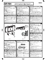
fig.5
fig.4
EXTENSION PACK
MoDEL no:
STR003E
carefully unpack the product and check the contents against
the list below. should any items be missing or damaged,
immediately contact with your sealey dealer.
Part Description ............................................................. Qty.
A
upright ..................................................................................2
B
Horizontal Brace .................................................................... 2
C
Diagonal Brace ...................................................................... 3
D
spacer ................................................................................... 2
E
rubber foot .......................................................................... 2
F
Bolt M8 x 50mm .................................................................... 6
G
M8 nut ...................................................................................6
H
Locking Pin .......................................................................... 12
I
cross Beam .......................................................................... 6
Original Language Version
Warning! Before assembly and use ensure you have read,
understood and apply Section 1 safety instructions.
1.1
It is recommended that this tyre racking system be assembled
by two people. When installing the cross beams it is advisable
to use a rubber mallet. Do not use a hard faced hammer as
this will damage the surface finish of the cross beams. Make
sure that all the clips lock in place securely and safety bolts are
fitted before using the unit. Do not use any parts that are
damaged and/or distorted as these may assemble incorrectly
and result in an installation that is unsafe and which may
cause injury or damage when the shelves are loaded.
1.2 Assembling the end frames. Refer to Fig.4.
1.2.1 Insert a rubber foot (E) into one end of each of the uprights (A1 & A2).
Note: Ensure that the end of the upright with the rubber
foot inserted is used as the base.
1.2.2 Place the uprights (A1 & A2) on the floor with the inner edges
facing each other and the rubber feet at the base.
1.2.3 take one horizontal brace (B1) and one spacer (D). Insert into
the upright (A2) at the base area drilled hole and loosely
secure using a M8 x 50mm bolt (f) and a M8 nut (G).
1.2.4 Place the other upright (A1) so that the horizontal brace (B1)
aligns with the base area drilled hole. take one of the diagonal
braces (c1) and insert into the upright (A1) so that hole aligns
with the hole in the horizontal brace (B1) and the drilled hole in
the upright (A1). Loosely secure using a M8 x 50mm bolt (f)
and a M8 nut (G).
1.2.5 Align the other end of the diagonal brace (c1) with the
corresponding hole in the opposite upright (A2). take another
diagonal brace (c2) and align with the same hole on diagonal
brace (c1) and on the upright (A2). Loosely secure using a M8
x 50mm bolt (f) and a M8 nut (G).
1.2.6 Align the other end of the second diagonal brace (c2) with the
corresponding hole in the opposite upright (A1). take a third
diagonal brace (c3) and align with the second diagonal brace
(c2). Loosely secure both to the upright (A1) using a M8 x
50mm bolt (f) and a M8 nut (G).
1.2.7 Align the remaining end of diagonal brace (c3) with the top
hole of the opposite upright (A2). Place a horizontal brace (B2)
aligned with the diagonal brace (c3) and across to the
opposite upright (A1). Loosely secure one end of horizontal
brace (B2), along with the diagonal brace (c3) to the upright
(A2) using a M8 x 50mm bolt (f) and a M8 nut (G). Align the
other end of the horizontal brace (B2) with the top hole of the
upright (A1). Place a spacer in the gap and loosely secure with
a M8 x 50mm bolt (f) and a M8 nut (G).
1.2.8 check that the assembled frame is square and tighten all the
fasteners.
1.3 Fitting the cross beams. Refer to Fig.5.
1.3.1
support one end frame in a vertical position and attach the end
of one cross beam (I) to it at the base of one of the uprights
(A). Ensure that both tags on the end bracket engage properly
with the slots in the upright. tap the cross beam gently next to
the end bracket so that the beam is properly seated into the
slots in the upright. Insert the locking pin (H) so that it is
against the beam. connect the other end of the beam to the
second end frame at the same height,tap into place and secure
with a locking pin (H).
1.3.2 Attach another cross beam (I) to the other side of the end
frames ensuring that it is at the same level as the first cross
beam.
1.3.3
continue to assemble the next two pairs of cross beams (I) at
the heights required. the end frames allow adjustment in 2"
increments. Each pair of beams must be mounted at the same
height. Ensure that all tabs on the cross beam brackets are
fully engaged in the slots in the uprights and that the cross
beams are properly tapped down into place then secured with
a locking pin.
1. ASSEMBLY
str003 & str003E IssuE 2 28/06/12