


NOTE:
It is our policy to continually improve products and as such we reserve the right to alter data, specifications and component parts without prior notice.
important:
no liability is accepted for incorrect use of this product.
warranty:
Guarantee is 12 months from purchase date, proof of which will be required for any claim.
sole uK distributor, sealey Group.
Kempson Way, suffolk Business Park,
Bury st. edmunds, suffolk.
iP32 7Ar
www.sealey.co.uk
01284 757500
01284 703534
web
environmental protection
recycle unwanted materials instead of disposing of them as waste. all tools, accessories and packaging should be
sorted, taken to a recycling centre and disposed of in a manner which is compatible with the environment.
when the product becomes completely unserviceable and requires disposal, drain off any fluids (if applicable)
into approved containers and dispose of the product and the fluids according to local regulations.
sm2503A, sm2503B issue:1 - 21/09/15
Original Language Version
© Jack sealey limited
7. maintenanCe
mmainaintenance
warning!
ensure the machine is unplugged from the mains power supply before attempting any maintenance.
for maximum performance it is essential that the lathe is properly maintained.
7.1.
lubricate the machine before every use. lubricate the bearings at either end of the leadscrew once or twice during the day if used
continuously. open the gear train cover to gain access to the left hand bearing. inject oil into the compound slide oilway located on the
slide front surface between the two hex socket cap screws.
7.2.
After each use remove all swarf from the machine and thoroughly clean all surfaces. if coolant has been used ensure it is all cleaned from
the machine and any collection tray is completely drained. lightly oil all machined surfaces.
7.3.
clean and coat the leadscrews with oil weekly.
7.4.
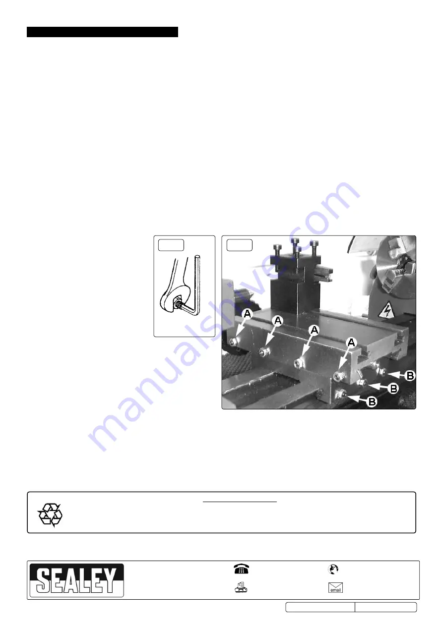
Cross slide and saddle adjustment.
Adjust the accuracy of the cross feed and saddle on a monthly basis. Any wear or slack can be
taken up by adjusting the position of the appropriate gib strip. to do this use a hex key and spanner as shown in fig.8. Adjust the cross
feed using the adjusters marked ‘A’ in fig.9.
7.4.1.
loosen the locking nuts on all four adjusters and screw them in evenly using the same torque. the slide should now be held firmly. test
by trying to turn the handle but do not force it to turn.
7.4.2.
now back off each gib screw by a quarter of a turn and tighten the lock nuts. test again by turning the handle. the movement should be
even and smooth along its whole travel.
7.4.3.
if the movement is too slack, screw all the adjusters in by one eighth of a turn until the correct adjustment is attained. tighten the lock
nuts.
7.4.4.
Adjust the saddle in the same way using the three adjusters marked ‘B’ in fig.9.
7.5.
Cross slide feed handle.
if any stiffness occurs in the operation of the handle it is usually as a result of swarf lodging between the
mating surfaces. remove the handwheel by undoing the securing screw and pull off the calibrated collar taking care to retain
the small spring plate which sits in a groove beneath the collar. clean the parts and reassemble in the reverse order taking
care to correctly reposition the spring.
fig. 8
fig. 9