9
Maintain the
cabinet in good condition Replace or repair damaged parts. Use genuine parts only. Unauthorised parts may be
dangerous and will invalidate the warranty.
9
locate cabinet in a suitable work area and keep area clean, tidy and free from unrelated materials. ensure there is adequate lighting.
9
Use only dry abrasives such as
proprietary brands of glass beads, silicon carbide, aluminium oxide and silica sand
. We recommend
Sealey item B5KG. Never use fluids or mix fluids with another media in the unit.
WARNING!
Always wear coveralls, approved eye or face and when operating the cabinet.
9
Keep the unit lid closed and secured when in use.
WARNING!
Ensure correct air pressure is maintained and not exceeded. (Max 90psi).
9
Always keep the blast nozzle directed at the workpiece. never use outside the unit and always use with the lid closed.
9
Regularly check that the exhaust vent at the back of the cabinet is clear and not blocked and that there is space between it and any
wall.
9
ensure the floor is clean and free from blasting media spillage; use a type “H” vacuum cleaner with a hepa filter.
9
Keep children and non-essential persons away from the work area.
9
When not in use disconnect from the electrical mains and the air supply.
8
DO NOT
clean up media spillage with a brush or compressed air.
8
DO NOT
use the cabinet for a task it is not designed to perform.
8
DO NOT
operate the cabinet if any parts are damaged or missing as this may cause failure and/or personal injury.
8
DO NOT
operate the cabinet with the lid open.
8
DO NOT
stand on the cabinet.
8
DO NOT
get the cabinet wet or use in damp or wet locations or areas where there is condensation.
8
DO NOT
operate the cabinet when you are tired or under the influence of alcohol, drugs or intoxicating medication.
8
DO NOT
leave the cabinet operating unattended.
2. INTRODUCTION
Steel cabinet with replaceable viewing screen and internal illumination. Fitted with shot blasting gun and suitable for proprietary brands of glass
beads, silicon carbide, aluminium oxide and silica sand only. excellent for a wide variety of workshop and bodyshop cleaning applications.
Requires a standard, dry workshop air supply. Supplied assembled and ready for use.
3. SpECIfICATION
Model no: ...................................................................
SB951
Air Consumption: ......................................................... 12cfm
door Size: .........................................................
530 x 440mm
doors: ..................................................................................1
Inlet Size: ..................................................................
1/4”BSP
n
ett Weight:
..............................................................
15.99Kg
operating Pressure: ......................................................
90psi
o
verall Dimensions (W x D x H):
.............
640 x 490 x 490mm
V
iewing Area: ....................................................
490 x 395mm
4. ASSEMBLy
4.1.
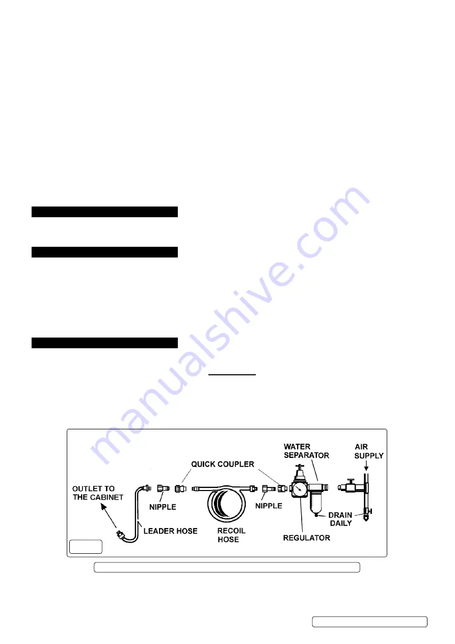
AIR SUppLy fIG.1
4.1.1.
You will require an air pressure of 60-90psi, and an air volume of 12cfm to operate the unit efficiently.
WARNING! Ensure air supply is clean, dry and does not exceed 90psi. Too high an air pressure and/or unclean or damp air will
shorten the product life due to excessive wear and may be dangerous, causing possible damage and/or personal injury.
4.1.2.
drain the air supply tank daily. Clean compressor air inlet filter weekly. For recommended hook-up see diagram below.
4.1.3.
Line pressure should be increased to compensate for unusually long air hoses (over 8 metres).The
minimum
hose and fittings
bore should be 10mm.
4.1.4.
Keep hoses away from heat, oil and sharp edges. Check hoses for wear and poor connections.
4.1.5.
Cabinet input connection is 1/4”BSP
.
4.2.
ASSEMBLy
4.2.1.
Unpack the product and check contents. Should there be any damaged or missing parts contact your supplier immediately.
4.2.2.
Push plastic suction hose (14) onto small diameter end of steel suction tube (15). Fit suction tube (15)
under clips in base of cabinet.
4.2.3.
Remove fitting (18) and one steel washer (17) from air hose connector (16), leaving on on
e steel washer (1
7) and rubber washer.
Put connector (16) through hole in side of cabinet and secure with washer (17) and fitting (18).
fig.1
Recommended hook up diagram
Note: Numbers in brackets refer to item numbers shown in the associated parts List.
S
B951.V5 Issue 3 (HF) 25/10/18
Original Language Version
© Jack Sealey limited


