p
WARNING!
Before operating the cutter ensure that you read, understand and apply Section 1 safety instructions. Ensure that the cutter is
disconnected from the power supply and air supply before moving or changing accessories.
If you have no cutting experience we recommend that you seek training from an expert before using this equipment. These Instructions cover
the operation of the plasma cutter but are not intended as a guide to the skills of cutting which are best obtained through practice.
5.1.
Locating the cutter
5.1.1. Ensure the work area has a good airflow and that there is no dust, smoke or gas present.
5.1.2. Ensure that there is a minimum clearance of 500mm around the cutter and that there are no obstacles to prevent a cool air flow.
Also check to ensure the front and rear louvres are not blocked.
5.1.3. When moving the cutter disconnect the unit from the mains power and the air supplies, and gather all cables and hoses safely.
5.2.
Connecting the earth cable
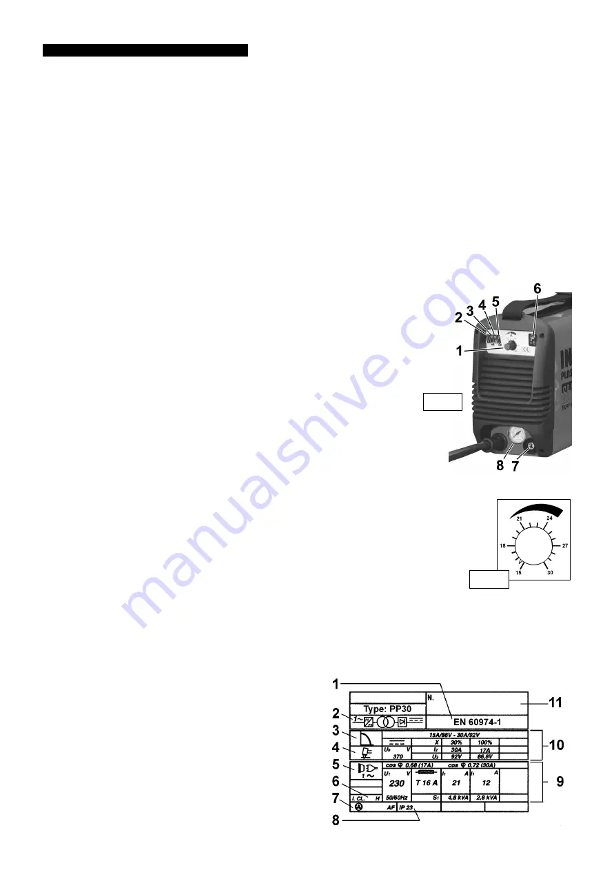
5.2.1. Connect the earth cable plug to the dinse socket on the cutter (fig. 1.7).
5.2.2. Connect the earth cable clamp to the workpiece or to the supporting metal workbench, checking that there is good electrical contact.
Caution: Ensure that there is good contact on oxidised or coated sheets.
5.2.3. Make the earth connection as close to the cutting area as possible.
5.2.4. DO NOT use metal structures or objects to make the earth contact, other than the workbench which is holding
the workpiece. To do so may endanger the system safety and could result in a poor cut.
DO NOT make the earth connection to that part of the workpiece which will become the off-cut.
5.3.
On/Off switch
The On/Off switched is located at the rear of the cutter. When the switch is in the O position the cutter is turned off. When switched
to the I position the cutter is turned on, which will be indicated by the green LED (fig. 1.5).
When switched on, the control and duty circuits are live but the torch will remain in stand-by mode (no voltage at the nozzle) until the
torch button is pressed.
5.4.
The cutting current regulator
The cutting current is regulated by a rotary switch (fig. 1.1 & fig. 2). The current required
depends upon the metal and thickness of the workpiece and the cutting speed.
5.5.
Air pressure
5.5.1. Check the specification to determine the air pressure required. Turn on air supply.
5.5.2. Pull and turn pressure regulator (para. 4.2.) knob On. Press down switch (fig. 1.6) and read
pressure gauge (fig. 1.8) whilst adjusting the regulator until the correct pressure is registered.
5.5.3. Push down the pressure regulator knob to lock it.
5.6.
The torch control
When the machine is turned on the green indicator light will show that the torch is
in stand-by mode.
5.6.1. Press the torch button and note the Pilot/Cutting Arc On signal is displayed by
a yellow LED (fig. 1.4). Releasing the button will interrupt the pilot or cutting arc.
5.6.2. As a safety feature, the torch will be automatically switched off -
a) during pre-air (0.3s) and post-air (>30s) phases.
b) if the nozzle is not moved to the workpiece within 2 seconds of pilot arc striking.
c) if the cutting arc is interrupted for any reason.
d) if the security system is activated.
5.7.
The thermal switch & mains voltage fault LED
If the thermal or mains fault red LED (fig. 1.2) illuminates and an alarm sounds, this will indicate one of the following:
a) The power transformer has overheated.
b) There has been a decrease or increase in the mains voltage power supplied to the cutter.
The operation of this switch is automatic and will stop all functions.
The problem that had caused this switch to activate is self rectifying, and within a few seconds the switch will
re-set and the red LED will go out. The cutter is now ready to use once again.
5.8.
Air pressure fault LED
The yellow LED (fig. 1.3) and red LED, (fig. 1.2) illuminated and the alarm activated indicates that
the air pressure is either too high or too low.
This activation will automatically stop the cutter operating.
Once the necessary adjustments to the air pressure have been made the fault signal will return to normal, the LED displays will go out,
and the cutter is ready for use again.
5.9.
The torch
Although the cutter may be fully powered, the torch button is the only device that will activate the cutting process.
5.9.1. To turn the cutting process on, the torch button must be fully depressed.
NOTE:
To minimise the possibility of accidental starting, the button must be depressed for at least half a second before the cutting operation will start.
5.9.2. Release the button and the cutting cycle will stop immediately. The cooling air (post-air) will continue to flow.
NOTE:
Longer than standard nozzles and electrodes are available (see
Parts List) to improve accessibility in awkward cutting positions.
5.10.
Ratings plate
On the rear of the cutter is the ratings plate giving the following data:
1 -The standard relating to the safety and construction of arc
welding and associated equipment.
2 - Single-phase static frequency converter-transformer-rectifier.
3 - Drooping current characteristic.
4 - Plasma cutting.
5 - Single-phase AC supply.
6 - Insulation thermal class.
7 - Forced (fan) air cooling.
8 - Rating of internal protection provided by casing.
5. CONTROL INSTRUCTIONS
PP30 - 1 - 130901
fig. 2
fig. 1


