


9.1.
Wire feed unit
Check the wire feed unit at regular intervals. The feed roller wire guide plays an important part in obtaining consistent results. Poor wire
feeding affects welding. Clean the rollers weekly, especially the feed roller groove, removing all dust deposits.
9.2.
Torch
Protect the torch cable from mechanical wear. Clean the liner from the machine forwards by using compressed air. If the liner is clogged it
must be replaced.
9.3.
Changing feed roller
IMPORTANT:
Adjust the feed roller to the corresponding wire size.
There are two grooves on the feed roller, 0.6mm and 0.9mm. Always use
the groove on the outside of the roller, (the groove nearest to you). To remove the feed roller, undo the two screws and remove the plastic
cover (fig. 12). Clean, turn or change the feed roller as appropriate and refit the plastic cover.
9.4.
Contact tip
(to remove tip follow steps in 4.3.5. to 4.3.8.).
The contact tip is a consumable item and must be replaced when the hole becomes enlarged or oval. The contact tip
MUST
be kept free from
spatter to ensure an unimpeded flow of gas.
9.5.
Gas cup
(to remove cup follow steps in 4.3.5. to 4.3.8.).
The gas cup must also be kept clean and free from spatter. Build up of spatter inside the gas cup can cause a short circuit at the contact tip
which will result in either the fuse blowing on the printed circuit card, or expensive machine repairs. To keep the contact tip free from spatter,
we recommend the use of Sealey Anti-Spatter Pressure Spray (MIG/722308) available from your Sealey Dealer.
9. MAINTENANCE
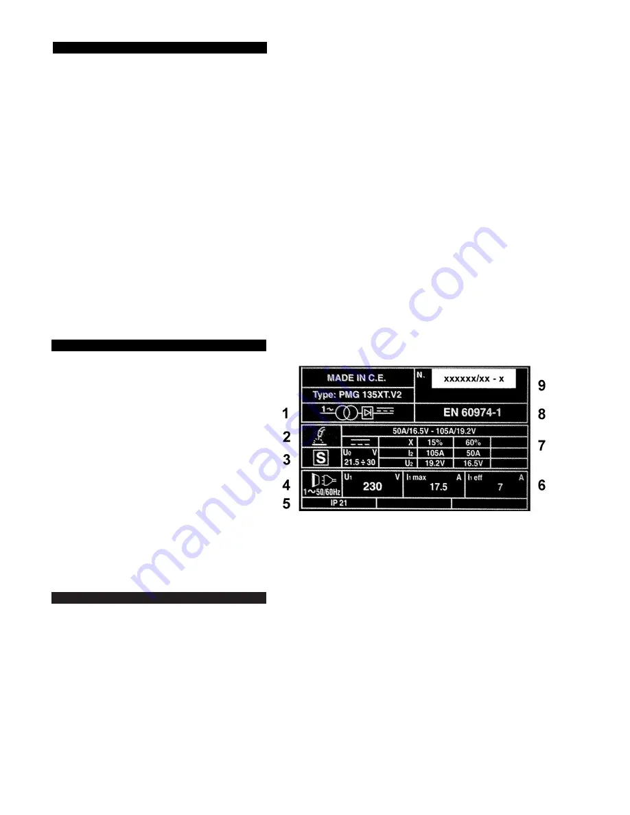
8. RATING PLATE
On the front of the welder is a rating plate, giving the
following data:
1 - Transformer-rectifier.
2 - Welding procedure: manual arc welding with covered electrode.
3 - S: Indicates that welding may be carried out in environments
with a heightened risk of electric shock e.g. very close
to large metallic objects.
4 - Power Supply Type: Single-phase AC.
5 - Rating of internal protection provided by casing.
6 - Power Supply
U
1
: Rated supply voltage.
I
max
: Maximum current.
I
1eff
: Maximum effective current.
7 - Output
U
0
: Maximum open-circuit voltage.
I
2
, U
2
: Current and corresponding voltage.
X: Welding ratio based on a 10 minute cycle. 30%
indicates 3 minutes welding and 7 minutes rest, 100% indicates continuous welding.
A/V-A/V: Welding current adjustment range and corresponding voltages.
8 - The standard relating to the safety and construction of arc welding, and associated, equipment.
9 - Serial Number. Specifically identifies each welder.
7.1.
Mig/Mag welding
A spool of welding wire is placed on spool holder and automatically fed through an insulated liner in the torch to its tip. The torch consists of a
switch, liner, gas hose (not PMG100) and control cable. The switch activates the wire feed roller and the gas flow. Releasing the switch stops wire
feed and gas flow. The weld current is transferred to the electrode (the wire) from the contact tip at the torch end. Four power settings (two settings
only on PMG100) increase or decrease the amperage transferred to the electrode. Settings (fig. 6) are Min & 1 (low) then Min/2, Max/1 to Max/2
(high). Wire speed must be adjusted according to power output. The higher the current the faster the wire speed. A gas cup fits over the contact tip to
direct the gas flow towards the weld ensuring the arc welding process is shielded from the oxidising air. The shielding gas also assists heating the weld
(fig. 11). The torch is connected to the positive output and the negative clamp is attached to the workpiece.
7.2.
Spot welding
Remove the gas cup and fit a spot welding gas cup. Turn the power and wire speed to the highest settings available. Drill a small hole in the top
workpiece. Push the gas cup onto the material to be welded. The castellations on the cup keep it the correct distance from the weld pool and
allow you to push the two pieces being welded together. Press the torch trigger and hold it for 1 to 3 seconds. Depending on the metal thickness,
the wire will feed through during the allotted time and create the weld.
7.3.
Preparations for welding
#
WARNING! ENSURE THAT THE MACHINE IS SWITCHED OFF AT THE MAINS. IF WELDING A VEHICLE, DISCONNECT THE
BATTERY OR FIT AN ELECTRONIC CIRCUIT PROTECTOR. ENSURE THAT YOU READ AND UNDERSTAND THE ELECTRICAL
SAFETY INSTRUCTIONS IN SECTION 1.
7.3.1. To ensure a complete circuit, the earth clamp must be securely attached to the workpiece.
1) The best connection is obtained by grinding the point of contact on the workpiece before connecting the clamp.
2) The weld area must also be free of paint, rust, grease, etc.
3) If welding a vehicle, disconnect the battery or fit an “Electronic Circuit Protector” (available from your Sealey dealer).
7.3.2. The following table is an estimated duration of cylinders based on a flow rate of 2ltr/min.
Actual duration will depend upon various job conditions including the operator’s welding technique. All times are, therefore, approximate.
a) Refillable cylinder:
CO
2
1000g = 3.3 hours. Refill service via local Sealey dealers.
b) Disposable cylinders:
CO
2
390g = 1-1/4 hours, 600g = 2 hours.
Argon 300g = 1 hour, CO
2
/Argon 300g = 1 hour Note:When comparing cylinder prices, always check fill weights.
7. MIG/MAG GAS WELDING PRINCIPLES
PMG100.V2, PMG110.V2, PMG135XT.V2, PMG155XT.V2 - 2 - 120407


