


5.6.13.
Slide the contact tip over the wire and screw back into position.
5.6.14.
Reattach the gas cup.
WARNING! DO NOT
turn the gas cup anti-clockwise. This will damage the internal spring.
5.6.15.
Cut the wire so that it is just protruding from the gas cup (fig.10).
5.7.
SETTING THE WIRE TENSION
5.7.1.
Adjust the wire tension by turning the wire tension knob (fig.8). Turn clockwise to increase the tension and anti-clockwise to decrease
the
tension.
IMPORTANT:
Too little or too much tension will cause problematic wire feed and poor weld quality.
5.7.2.
Tension between rollers is checked by slowing down the wire between your gloved fingers. If the top feed rollers skid the tension is
correct. Use as low a tension as possible; too high a tension will deform wire and result in a blown fuse on the printed circuit board.
Adjust tension by turning the pressure knob (fig.8).
5.8.
TURNING/CHANGING THE DRIVE ROLLER
NOTE:
Ensure that the contact tip, the groove size on the drive wheel and torch liner correspond to the wire diameter being used. Failure
to do this could cause the wire to slip and/or bind.
5.8.1.
Open the wire feed mechanism. See section 5.6.1.
5.8.2.
Unscrew and remove the black feed roller retaining knob (fig.8), and put to one side.
5.8.3.
The roller carrier (fig.11) is keyed to the main drive shaft.
5.8.4.
With care slide the slide the drive roller off the drive shaft. Ensure the key bar remain in place (fig.12).
NOTE:
The size of each wire feed groove is marked on the edge of the roller on the same side as the groove.
5.8.5.
Reverse or replace the drive roller as required. The required groove should be positioned furthest away from you and be in line with the
drive
path.
5.8.6.
Replace the drive roller. Ensure that the keyway is aligned.
5.8.7.
Reattach the black feed roller retaining knob and tighten.
5.8.8.
Close the wire feed mechanism. See section 5.6.7
5.9.
WIRE FEED CONTROL
5.9.1.
Select the desired wire feed with the ‘Wire Feed Control’ control located on the front panel of the welding set (fig.13).
5.10.
GASLESS WELDING
5.10.1.
Disconnect gas hose (fig.4) from cylinder. Store cylinder in safe dry childproof location.
5.10.2.
Connect polarity cable to suit gasless welding. See section 5.2.2.
5.10.3.
Ensure that the contact tip, the groove size on the drive wheel and torch liner correspond to the wire diameter being used.
5.11.
MANUAL METAL ARC WELDING (MMA)
NOTE:
Before connecting cables it is important to read and fully understand the electrode manufacturer’s instructions on the
electrode packaging. This will indicate the correct polarity connection for the electrode, together with the most suitable current to use.
In principle, when ARC welding the Electrode Holder ”POSITIVE” is normally connected to the “POSITIVE” (+) terminal (fig.2).
The EARTH CLAMP cable is connected to the terminal not occupied by the electrode holder cable.
The clamp is connected to either:
a) The work piece.
b) A metallic work bench. The connection must be as close to the proposed weld as possible.
WARNING!
Cable connectors must be turned into the quick plugs fully to ensure a good electrical contact. Loose connections will
cause overheating, rapid deterioration and loss in efficiency.
DO NOT
use welding cables over 10m in length.
With the exception of a metallic workbench
DO NOT
connect the return cable to any metallic structure which is not part of the
workpiece, as this may be dangerous.
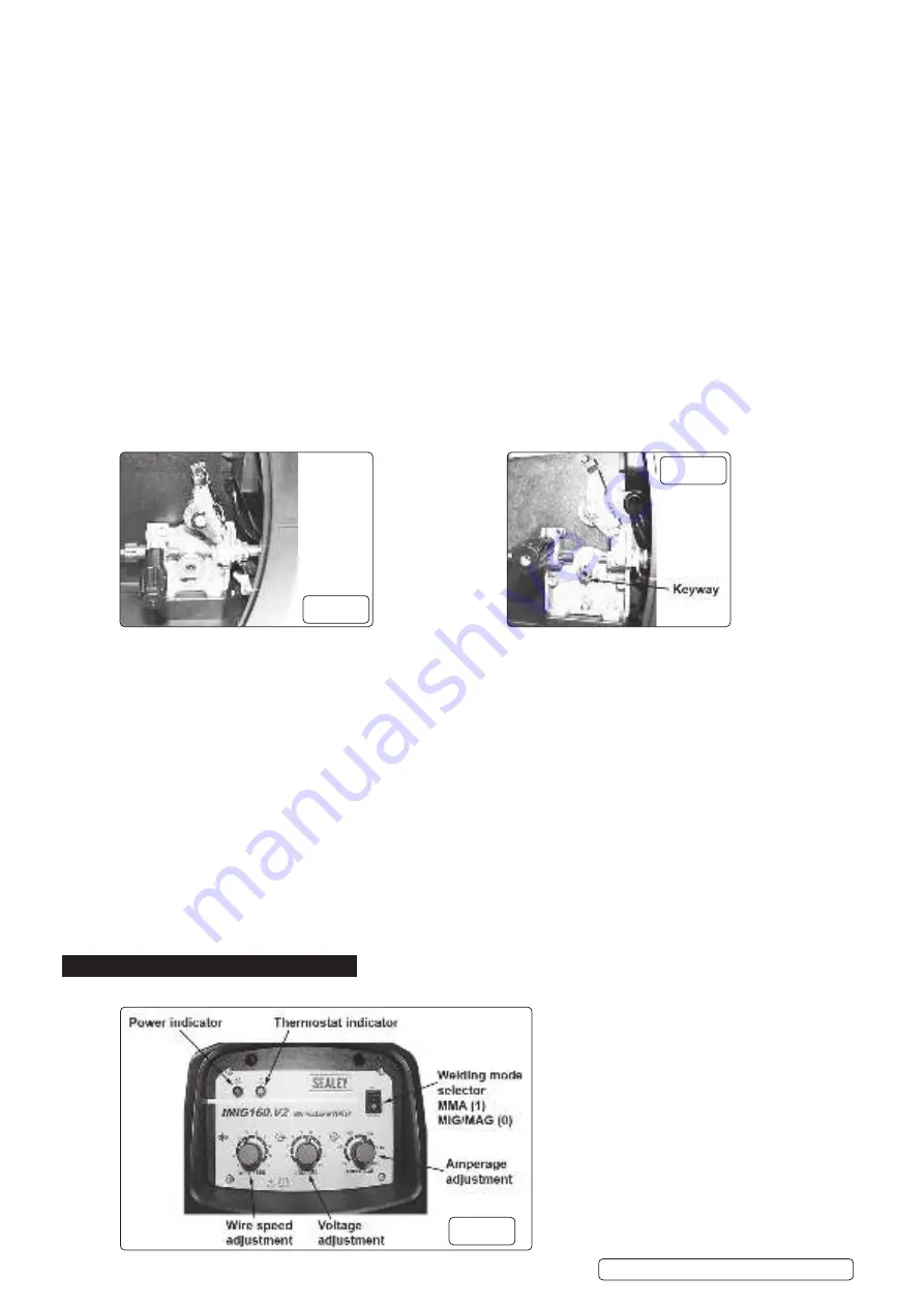
6. CONTROLS
6.1.
Fig 13 illustrates the main panel control for IMIG160.V2. The panel control for IMIG180.V2 is identical.
fi
g.11
fi
g.12
fi
g.13
IMIG160.V2, IMIG180.V2 Issue 1 14/01/22
Original Language Version
© Jack Sealey Limited


