Rated on-load voltage
U
o
in
V
a) Peak value in case of direct current;
b) Peak & r.m.s. value in case of alternating current.
KVA
ED %
1
2
Rated weld current
U
2
Conventional load voltage
Mains supply and number of
phases (i.e. 1 or 3) with symbol
for alternating current.
PA
KVA
COS
U
1
... V/...Hz
Rated values of the supply voltage and the
frequency.
/
Rated supply current.
IP
Degree of protection, i.e. 21 or 23.
Welding power sources which are suitable
for supplying power to welding operations
carried out in an environment with increased
hazard of electric shock.
6. 1. Wire feed unit
Check the wire feed unit at regular intervals. The feed roller wire guide plays an important part
in obtaining consistent results. Poor wire feeding affects welding. Clean the rollers weekly,
especially the feed roller groove, removing all dust deposits.
6. 2. Torch
Protect the torch cable assembly from mechanical wear. Clean the liner from
the machine forwards by using compressed air. If the liner is clogged it must be replaced.
6. 3. Turning or Changing the Feed Roller
s
s
s
IMPORTANT:
Adjust the feed roller to the corresponding wire size.
There are two grooves on the feed roller, 0.6mm and 0.8mm. Always use the groove on the outside
of the roller, (the groove nearest to you). To remove the feed roller see fig 7.
Clean and turn, or if damaged change the feed roller.
6. 4. Contact Tip
(to remove tip follow steps in 3.3.6. and to replace 3.3.9. a & b very carefully).
The contact tip is a consumable item and must be replaced when the hole becomes enlarged or oval. The contact tip
MUST
be kept free from
spatter to ensure an unimpeded flow of gas.
6. 5. The Gas Cup (Conical Nozzle)
(to remove cup follow steps in 3.3.6. and to replace 3.3.9. a & b very carefully).
The gas cup must also be kept clean and free from spatter. Build up of spatter inside the gas cup can cause a short circuit at the contact tip
which will result in either the fuse blowing on the printed circuit card, or expensive machine repairs. To keep the contact tip free from spatter, we
recommend the use of Sealey anti-spatter spray (MIG/722307) available from your Sealey Dealer. We also recommend that you keep spare tips
and gas cups in stock.
6. 6. Replacing the Liner
Wind the wire back on to the spool and secure it. Remove torch from front panel by undoing knurled knob. Pull out torch and undo the brass nut.
Pull out liner and replace with a new one.
6. 7
Changing gears
An inexperienced welder can allow spatter to build up in the tip and shroud. In severe cases this can block the feed causing gear stripping in the
drive motor. To check if the gears are worn depress the button on the torch with the set switched on. If the gears are warn, a grating sound will
be heard coming from the wire feed motor, you may also observe the feed roller vibrating instead of rotating. Should this be the case, open the
gearbox, remove the worn or damaged gears and replace with new ones.
6. 8. Changing Fuses
The fuse is located on the front panel. Fuses are mainly blown for the following reasons:
3
Spatter collecting in the gas cup and contact tip causing a short circuit.
3
Wire tension is too great.
3
A sudden surge of current.
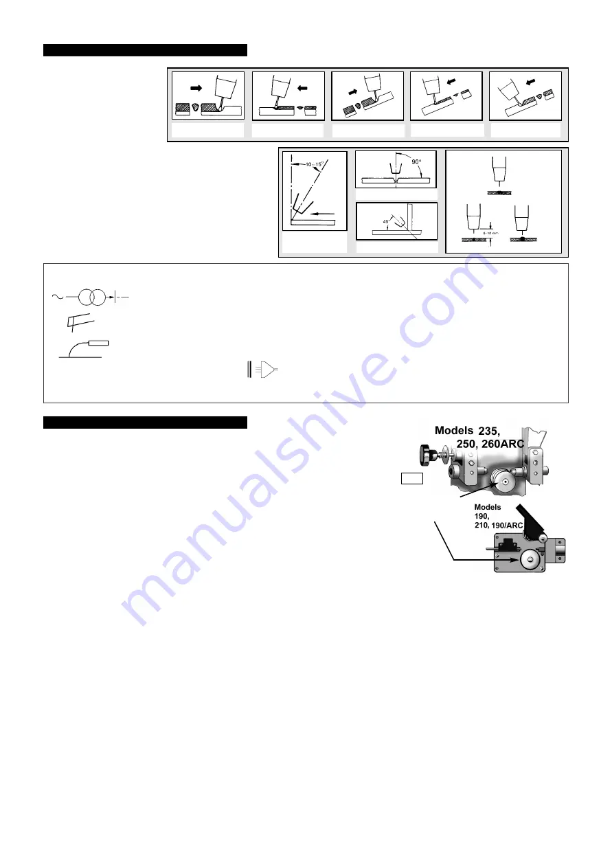
The position of the torch,
its angle and direction of travel
in relation to the workpiece
is essential for the appearance
and quality of the weld.
Illustrations demonstrate
various positions and
directions.
Rightward Welding
Welding in general
Welding with a long arc reduces penetration and widens
the arc.
This in turn results in more spatter.
A long welding arc can be appropriate for welding butt
joints in thin materials.
Welding with a short arc
(at the same weld settings
)
results in greater penetration and a narrower weld
and reduces the amount of spatter.
Leftward Welding
Vertical Rightward Downhard leftward
Down Rightward
5. VARIOUS WELDING METHODS
6. MAINTENANCE
fig 7
MEANINGS OF MARKINGS, AND SYMBOLS
Single-Phase
transformer
Flat Characteristic
MIG/MAG welding
...A/ ... V to ...A/ ... V
Range of output, rated min
& max welding current and
their corresponding
conventional load voltage.
1. Direction of
Welding
3. Fillet Weld
3. Butt Weld
Normal
Welding
Arc
Short
Welding
Arc
Long
Welding
Arc
To remove roller
locate and undo the
hex nut on the side
of the roller
AUTOMIGS 190,210,235,250, 190ARC & 260ARC - (0095) - (1) - 010299


