

NOTE: It is our policy to continually improve products and as such we reserve the right to alter data, specifications and component parts without prior notice.
IMPORTANT:
no liability is accepted for incorrect use of this product.
WARRANTY:
Guarantee is 12 months from purchase date, proof of which will be required for any claim.
INFORMATION:
for a copy of our latest catalogue and promotions call us on 01284 757525 and leave your full name and address, including postcode.
01284 757500
01284 703534
Sole UK Distributor, Sealey Group,
Kempson Way, Suffolk Business
Park
,
Bury St. Edmunds, Suffolk,
IP32 7AR
www.sealey.co.uk
W e b
Original Language Version
VS2030 Issue: 1 - 21/11/12
© Jack Sealey limited
6. MAINTENANCE
6.1
Always keep the plastic adaptors clean and free of oil and grease. clean them regularly with a non-aggressive cleaner,
ensuring dry before storage.
5.1
follow the manufacturer's instructions for the removal, if required, of the device or hose to be tested. Use a damp cloth or
gloves and arm protection if the system is known to be hot.
5.2
connect an air line with known air pressure to the regulator of the tester with the ball valve shut (operating lever at 90° to
hose axis).
IMPORTANT! Regulate air pressure in tester to 25psi maximum.
Refer to manufacturer's manual relating
to the maximum air pressure of the turbo or other system being tested. over pressurisation may damage system
components. for example the maximum pressure in most vehicle turbo systems is approximately 15psi (1bar) up to 25psi
(1.7bar). A vehicle coolant system is typically rated at 15psi.
A graduated
approach to leakage testing is recommended.
5.3
Method
5.3.1
Select the correct air inlet spigot adaptor and plug adaptor by first measuring the orifice diameter and then couple the
tester hose to the selected air inlet adaptor. Each adaptor has three stepped tapered sides to facilitate three sizes,
insertion, sealing and gripping.
5.3.2
Set regulator of tester to 5psi to check for large leaks with valve shut (operating lever at 90° to hose axis).
5.3.3
Plug the exit orifice of the system with the plug adaptor.
5.3.4
connect the inlet adaptor set at 5psi to the entry orifice of the system.
5.3.5
open valve fully (operating lever in line with hose axis) to check for leaks and or pressurisation up to pre-set (5psi). If a
leak is found, by listening or if the pointer falls, it indicates that the system has a leak resulting in loss of pressure. Repair
the leak and retest.
5.3.6 If no leaks are evident, regulate pressure to 10psi and check for leaks and or pressurisation up to pre-set (10psi). If a
leak is found, by listening or if the pointer falls, it indicates that the system has a leak resulting in loss of pressure. Repair
the leak and retest.
5.3.7 If no leaks evident, regulate pressure to a maxmum of 15psi or to the manufacturer's maximum pressure and retest. If a
leak is found, by listening or if the pointer falls, it indicates that the system has a leak resulting in loss of pressure. Repair
the leak and retest. If the gauge pointer remains stationary for one minute it will indicate that the system is in good
working order.
5.3.8
Release pressurised system by rotating the ball valve lever to align with hose axis.
5.3.9 disconnect the quick coupler, clean and return all items to carry case.
5. OPERATION
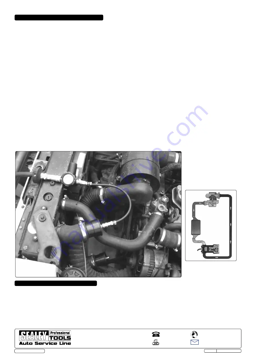
Example (left) shows the
kit testing a turbo system
intercooler coil for integrity.
Intercooler
coil
turbo
Engine
System schematic


