

AK452X & AK453X - 0444 - (2) - 140700
p
p
WARNING!
Ensure the pump is disconnected from the air line before attempting any service or maintenance.
6.1.
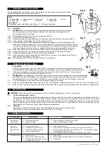
Air line lubricator (fig 3. item A).
This unit is designed to automatically lubricate the pump by the air intake. The unit must be kept topped up with good quality air oil
(our reference: ATO/500 500ml size or ATO/1000 1ltr size). To adjust the oil flow turn the oil regulator on the top of the unit. Turn screw
towards marking (+) will to increase the flow and towards (-) will to decrease flow. To change and clean the oil unit unscrew the bowl
and be careful to keep the sealing ring safe. Empty, clean and re-fill to maximum line and replace ensuring the sealing ring correctly.
Finger tighten only. Contact your Sealey dealer for parts and information.
6.2.
Cleaning.
Clean pump and air units with clean damp cloth. Mild detergents may be used to remove grease.
DO NOT use solvents or abrasives and do not get the pump or air units wet.
6. MAINTENANCE
Air regulator
Set the air regulator (fig 3. item A) at 7.9bar/115psi. It is important to maintain the correct operating pressure
to ensure that the control valves and connectors are not damaged, and to prevent leakage in the delivery lines.
5.1.
If you need to adjust the air pressure identify the tap on top of unit (fig 3. item D & fig 4). Pull tap up (fig 4)
and turn whilst monitoring the pressure gauge (fig 3. item C).
p
WARNING!
When exchanging a polycarbonate bowl ensure the suction tube is protected to avoid dirt particles being
transmitted to a new bowel. Always clean new delivery lines ensuring all metal shavings have been removed before
connecting the pump and control valves. Failing to do so may damage the unit and will invalidate your warranty.
5.2.
Turn the air pressure on and check to ensure there are not leaks in the system.
5.3.
Prime unit by operating grease control valve (fig 2. item 9) until lubricant emerges from end of the gun. The unit is now ready for use.
5.4.
When not in use, turn the air supply off and disconnect the unit from the air supply. Store the grease unit in a safe, clean, dry, childproof area.
5. OPERATING INSTRUCTIONS
4.2.
Installation.
p
WARNING!
Clean new delivery lines ensuring all metal shavings have been removed before
connecting the pump and control valves. Any dirt in the inlet hoses will damage the unit
and may invalidate your warranty.
4.2.1. Fit the follower plat (fig 2 item 1) in the the grease bucket (2).
4.2.2. Fit the lid (3) to the pump shaft (4).
4.2.3. Attached the grease hose assembly (5) to the grease outlet (6) at the base of the pump body (7).
4.2.4. Screw the large 1/4bsp fitting (E1) into the air pump inlet (F).
4.2.5. Connect the two parts of the air regulator system together by using the small 1/4bsp fitting (fig 4. E2).
Screw the air regulator system (fig 3. A) to the pump fitting (E1) ensuring that the lubrication bowl (B)
is nearest to the pump head. Ensure the air flow arrows on each part of the air regulator are pointing
in the same direction, and that the unit is installed with the arrows pointing toward the pump inlet.
4.2.6. Screw the pressure dial (C) into the side of the air regulator that is appropriate for you to read.
4.2.7. Connect the external air line system to the regulator inlet (G) and set the dial (C) to 90psi.
4.2.8. To adjust the pressure raise the control knob (D) (see chapter 5).
4.2.9. The air regulator oil supply required to lubricate the pump is minimal. Turn adjusting screw (fig 4.H)
fully home and then open by 1/4 of a turn.
Note:
We recommend that PTFE sealing tape is used on all connections.
fig 4.
4. ASSEMBLY & INSTALLATION
4.1. Contents:
Remove items from carton. Identify (fig 2) and check pieces for damaged. Contact
supplier immediately if you experience a problem.
Fig 2.
1. Follower plate
2 Grease bucket
3. Dust cover
4. Pump shaft
5. Hose
6. Grease outlet
7. Pump
8. Z-swivel
9. Grease gun
Fig 3. item A.
Air regulator system with male air line fittings. & Trolley (not illustrated).
fig 2.
fig 3.
7. TROUBLE SHOOTING
THE PROBLEM
THE CAUSE
THE SOLUTION
1. Air motor does
not operate.
2. Air motor
operates but
the pump does
not.
3. Poor performance
1.1. Air pressure is too low.
1.2. Muffler is blocked.
2.1. Strainer tube blocked.
2.2. Temperature of grease too low.
2.3. Air pockets in grease container.
2.4. Grease container dented.
3.1. Muffler blocked.
3.2. Temp too low. Viscosity too high.
3.3. Distance between pump and control
discharge valve too long.
1.1. Adjust air pressure to Minimum 8bar 120psi.
1.2. Remove muffler clean and replace.
2.1. Clean strainer parts item
2.2. Remove drum to warmer area allow temp of grease to rise above 15
O
C
2.3. Viscosity too high. Temperature must be above 15
O
C. Then compact the grease
by pushing the follower plate down.
2.4. Push the follower plate down past the dented area of the container.
3.1. Clean
muffler.
3.2. Increase grease temperature above 15
O
C by moving to warmer area.
3.3. Shorten hose.