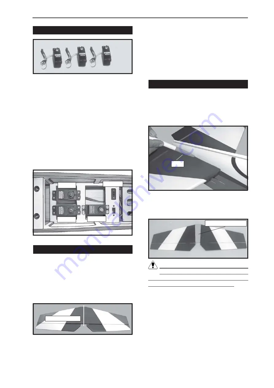
1) Install the rubber grommets and brass
collets onto the elevator, rudder and throttle
servos. Test fit the servos into the preinstalled
servo tray. Because the size of servos dif-
fer, you may need to adjust the size of the
precut openings in the tray.
2) Position the servos into the servo tray
with the output shafts orientated as shown
below. Drill 1/16” pilot holes through the tray
for each of the mounting screws.
INSTALLING THE FUSELAGE SERVOS.
Secure the servos with the screws pro-
vided from your radio system.
1) Using a ruler and a pen, locate the
centerline of the horizontal stabilizer, at the trail-
ing edge, and place a mark. Use a triangle
and extend this mark, from back to front,
across the top of the stabilizer. Also extend
this mark down the back of the trailing edge of
the stabilizer.
ALIGNING THE HORIZONTAL STABILIZER.
2) Using a modeling knife, carefully re-
move the covering from over the vertical sta-
bilizer mounting slot in the top of the fuselage.
4) When you are satisfied with the align-
ment, hold the stabilizer in place with T- pins
or masking tape, but do not glue at this time.
MOUNTING THE HORIZONTAL STABILIZER.
1) With the stabilizer held firmly in place,
use a pen and draw lines onto the stabilizer
where it and the fuselage sides meet. Do this
on both the right and left sides and top and
bottom of the stabilizer.
2) Remove the stabilizer. Using the lines
you just drew as a guide, carefully remove the
covering from between them using a model-
ing knife.
When cutting through the covering to re-
move it, cut with only enough pressure
to only cut through the covering itself. Cutting
into the balsa structure may weaken it.
Remove covering.
3) Using a modeling knife, carefully re-
move the covering that overlaps the stabilizer
mounting platform sides in the fuselage. Re-
move the covering from both the top and the
bottom of the platform sides.
4) When you are sure that everything is
aligned correctly, mix up a generous amount
of 30 Minute Epoxy. Apply a thin layer to the
top and bottom of the stabilizer mounting area
and to the stabilizer mounting platform sides
Draw center line.
Pen.
3) Slide the stabilizer into place in the pre-
cut slot in the rear of the fuselage. The stabi-
lizer should be pushed firmly against the front
of the slot.
Throttle.
Elevator.
Rudder.
Switch.
18
Содержание SEA12
Страница 14: ...Instruction Manual M3x15mm 11cm Epoxy 14 ...
Страница 15: ...Speed control Battery M3x15mm 15 Air exit hole ...


