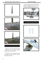
45
FLIGHT PREPARATION.
PREFLIGHT CHECK.
Check the operation and direction of the
elevator, rudder, ailerons and throttle.
A) Plug in your radio system per the
manufacturer’s instructions and turn eve-
rything on.
B) Check the elevator irst. Pull back
on the elevator stick. he elevator halves
should move up. If it they do not, lip the
servo reversing switch on your transmit-
ter to change the direction.
C) Check the rudder. Looking from be-
hind the airplane, move the rudder stick
to the right. he rudder should move
to the right. If it does not, lip the servo
reversing switch on your transmitter to
change the direction
.
D) Check the throttle. Moving the
throttle stick forward should open the
carburetor barrel. If it does not, lip the
servo reversing switch on your transmit-
ter to change the direction.
E) From behind the airplane, look at the
aileron on the right wing half. Move the
aileron stick to the right. he right ailer-
on should move up and the other aileron
should move down. If it does not, lip the
servo reversing switch on your transmit-
ter to change the direction.
1) Completely charge your transmit-
ter and receiver batteries before your irst
day of lying.
2) Check every bolt and every glue
joint in the
Giant Zero A6M Gas ARF
50-60cc, 86”
to ensure that everything is
tight and well bonded.
3) Double check the balance of the air-
plane. Do this with the fuel tank empty.
4) Check the control surfaces. All
should move in the correct direction and
not bind in any way.
5) If your radio transmitter is equipped
with dual rate switches double check that
they are on the low rate setting for your
irst few lights.
6) Check to ensure the control sur-
faces are moving the proper amount
for both low and high rate settings.
7) Check the receiver antenna. It should
be fully extended and not coiled up in-
side the fuselage.
We wish you many safe and enjoyable lights
with your
Giant Zero A6M Gas ARF 50-60cc, 86”
.
8) Properly balance the propeller. An
out of balance propeller will cause exces-
sive vibration which could lead to engine
and/or airframe failure.
Содержание SEA 334
Страница 11: ...11 5 6 7 8 2 3 4 Epoxy 9 ...
Страница 12: ...Giant Zero A6M Gas ARF 50 60cc 86 Instruction Manual 12 13 17 10 14 11 15 12 16 Mark 2mm 3x15mm ...
Страница 14: ...Giant Zero A6M Gas ARF 50 60cc 86 Instruction Manual 14 28 25 29 26 30 27 31 3x10mm ...
Страница 15: ...15 1 1 2 3 4 2 WING ASSEMBLY ASEMBLE BOMB INTO THE WING 3 3x15mm ...
Страница 20: ...Giant Zero A6M Gas ARF 50 60cc 86 Instruction Manual 20 14 18 11 15 12 16 13 17 170mm Pushrod wire ...
Страница 21: ...21 22 19 23 21 25 20 24 Ignition Modude Pen 26 ...
Страница 23: ...23 COWLING Please see below pictures 1 4 5 6 7 2 3 3mm Epoxy ...
Страница 28: ...Giant Zero A6M Gas ARF 50 60cc 86 Instruction Manual 28 7mm 14 18 19 20 15 16 17 13 Blind nut M5x20mm 170mm ...
Страница 30: ...Giant Zero A6M Gas ARF 50 60cc 86 Instruction Manual 30 2 6 3 7 4 8 5 9 Epoxy ...
Страница 31: ...31 10 11 1 INSTALL RUDDER CONTROL HORN Epoxy 2 3 6 4 5 Epoxy Epoxy ...
Страница 33: ...33 8 10 9 11 Epoxy 2 1 12 3 INSTALL ELEVATOR CONTROL HORN Epoxy ...
Страница 35: ...35 4 1 2 ELEVATOR PUSHROD HORN INSTALLATION 3 1 2 3 INSTALL ELEVATOR CONTROL HORN ...
Страница 37: ...37 5 6 7 8 9 10 1 INSTALLATION COCKPIT PILOT AND CANOPY Locate items necessary to install Epoxy ...
Страница 41: ...41 3 4 5 6 Wing bolt 7 8 9 10 hen install wing guns on the wings ...


