background image

www.modellmarkt24.ch

JU-87

Instruction Manual.

16

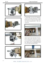
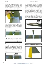
INSTALLING THE FUSELAGE SERVOS.

.

        Because the size of servos difer, you
may need to adjust the size of the precut 
opening in the mount. he notch in the 
sides of the mount allow the servo lead to 
pass through.

1) Install the rubber grommets and brass
collets into all servos. Test it the servo 
into the fuselage servo mount.

2) Secure the servos with the screws pro-
vided with your radio system.

hrottle servo.

THROTTLE SERVO ARM                         

INSTALLATION.

  Install adjustable servo connector in the 
servo arm as same as picture below:

Servo arm.

Adjustable servo 

connector.

Loctite secure.

hrottle servo arm.

INSTALLING THE RECEIVER SWITCH.

   Install the switch into the precut hole in 
the side, in the fuselage.

 3/32” Hole.

Trim and cut.

Epoxy.

www.modellmarkt24.ch

Содержание JU-87 STUKA GIANT SCALE

Страница 1: ...phics and speciications may change without notice JU 87 STUKA GIANT SCALE Speciications Wingspan 90 in 228 6 cm Wing area 1328 7 sq in 85 7 sq dm Weight 17 6 lbs 8 0 kg Length 68 3 in 173 4 cm Gasoline Engine 38 50cc Radio 7 channels with 7 servos www modellmarkt24 ch ...

Страница 2: ...lp you build a great lying aeroplane Please read this manual throughly before starting assembly of your JU 87 Use the parts listing below to indentify all parts Please be aware that this aeroplane is not a toy and if assembled or used incorrectly it is capable of causing injury to people or property WHEN YOU FLY THIS AEROPLANE YOU ASSUME ALL RISK REPONSIBILITY If you are inexperienced with basic R...

Страница 3: ...5 minute epoxy Hand or electric drill Assorted drill bits Modelling knife Straight edge ruler 2mm ball driver Phillips head screwdriver 220 grit sandpaper 90 square or builder s triangle Wire cutters Masking tape T pins hread lock Paper towels 38 50cc gasoline engine Computer radio with 7 servos Glow plug to suit engine Propeller to suit engine Protective foam rubber for radio system HINGING THE A...

Страница 4: ...www modellmarkt24 ch JU 87 Instruction Manual 4 HINGING THE FLAP www modellmarkt24 ch ...

Страница 5: ...xy Epoxy Aileron control horn Flap control horn Epoxy Epoxy Fiberglass control horn Fiberglass control horn INSTALL FLAP CONTROL HORN INSTALL LED LIGHT Install the lap control horn using the same method as same as the aileron con trol horns www modellmarkt24 ch ...

Страница 6: ...INGING THE FLAP FOR CENTER WING 1 Repeat steps to install hinging for center wing as same as steps done for ai lerons 2 hen it the joiner wire into the lap of center wing as below pictures 3 Slide the wing tube into the wing tube socket www modellmarkt24 ch ...

Страница 7: ...to adjust the size of the precut opening in the mount he notch in the sides of the mount allow the servo lead to pass through 1 Using a small weight Weighted fuel pick up works well and string feed the string through the wing as indicated 2 Place the servo between the mounting blocks and space it from the hatch Use a pencil to mark the mounting hole loca tions on the blocks www modellmarkt24 ch ...

Страница 8: ... secure the connec tion so they cannot become unplugged 6 Secure the servo to the aileron hatch using Phillips screwdriver and the screws provided with the servo 7 Apply 1 2 drops of thin C A to each of the mounting tabs Allow the C A to cure without using accelerator 8 Remove the string from the wing at the servo location and use the tape to at tach it to the servo extension lead Pull the lead th...

Страница 9: ...ce and use a Phillips screw driver to install it with four wood screws INSTALLING THE FLAP SERVO Repeat the procedure as above for the lap servo 2x10mm AILERON PUSHROD INSTALLATION Please see below pictures 100mm M3 clevis M3 lock nut www modellmarkt24 ch ...

Страница 10: ...www modellmarkt24 ch JU 87 Instruction Manual 10 INSTALLING THE FLAP PUSHROD INSTALLING THE LANDING GEAR Repeat the procedure as aileron push rod 100mm M3 clevis M3 lock nut www modellmarkt24 ch ...

Страница 11: ...www modellmarkt24 ch 11 2mm 2mm www modellmarkt24 ch ...

Страница 12: ...www modellmarkt24 ch JU 87 Instruction Manual 12 2mm 3x10mm www modellmarkt24 ch ...

Страница 13: ...www modellmarkt24 ch 13 2mm 3x10mm www modellmarkt24 ch ...

Страница 14: ...www modellmarkt24 ch JU 87 Instruction Manual 14 INSTALLING THE BOMB ON THE WINGS Epoxy Epoxy www modellmarkt24 ch ...

Страница 15: ...www modellmarkt24 ch 15 Epoxy www modellmarkt24 ch ...

Страница 16: ...brass collets into all servos Test it the servo into the fuselage servo mount 2 Secure the servos with the screws pro vided with your radio system hrottle servo THROTTLE SERVO ARM INSTALLATION Install adjustable servo connector in the servo arm as same as picture below Servo arm Adjustable servo connector Loctite secure hrottle servo arm INSTALLING THE RECEIVER SWITCH Install the switch into the p...

Страница 17: ...ING THE ENGINE SWITCH Trim and cut 3 Carefully bend the second tube up at a 45º angle his tube is the vent tube 4 Test it the stopper assembly into the tank It may be necessary to remove some of the lashing around the tank opening using a modeling knife If lashing is present make sure none falls into the tank Vent tube Fuel ill tube Fuel pick up tube 5 With the stopper assembly in place the weight...

Страница 18: ...ubes in the stopper Once the tank is installed inside the fuselage it may be diicult to determine which is which 7 Slide the fuel tank into the fuselage Guide the lines from the tank through the hole in the irewall 8 Connect the lines from the tank to the en gine and muler he vent line will connect to the muler and the line from the clunk to the carburetor Vent tube Fuel pick up tube Fuel ill tube...

Страница 19: ...www modellmarkt24 ch 19 5x100 mm 8mm Blind nut 6 5 mm 6 5 mm www modellmarkt24 ch ...

Страница 20: ...tle stick and trim and install the servo horn perpendicular to the servo center line 2 Movethethrottlesticktotheclosedpo sition and move the carburetor to closed Use a 2 5mm hex wrench to tighten the screw that secures the throttle pushrod wire Make sure to use threadlock on the screw so it does not vibrate loose 170mm www modellmarkt24 ch ...

Страница 21: ...ry to in stall the electric power conversion parts included with your model Motor 360 6000 Watt Propeller 24x10 25x12 ESC 160A 200A Lipo 12S 3 Attach the electric motor box to the irewall suitable with the cross lines drawn on the electric motor box and ire wall Using M5x25mm to secure the mo tor box to the irewall Please see pictures below 6 5mm 6 5mm www modellmarkt24 ch ...

Страница 22: ...20mm hex head bolts to se cure the motor Please see picture shown M5x25mm Blind nut M5x20mm 5 Attach the speed control to the side of the motor box using two sided tape and tie wraps Connect the appropriate leads from the speed control to the mo tor Make sure the leads will not interfere with the operation of the motor 170mm www modellmarkt24 ch ...

Страница 23: ...3 COWLING 1 Tape the cowl to the fuselage using low tack tape 2 Use a drill and drill bit to drill the holes for the cowl mounting screws Make sure the cowl position is correct before drill ing each hole www modellmarkt24 ch ...

Страница 24: ...de the muler screws through the engine Place the mulr extension and gaskets included with the engine on the screws Be careful when mounting the cowl so the screws and extension remain in position until the mulr can be at tached 3x10mm www modellmarkt24 ch ...

Страница 25: ...inner cone If it does use a sharp modeling knife and carefully trim away the spinner cone where the propel ler comes in contact with it Insert plastic cover on the cowling Epoxy HINGING THE ELEVATOR Glue the elevator hinges in place using the same techniques as below pictures www modellmarkt24 ch ...

Страница 26: ...ass control horn Epoxy Elevator iberglass control horn Epoxy HINGING THE RUDDER Glue the top three rudder hinges in place using the same techniques used to hinge the elevator he lower hinge will be glued when the in rudder assembly is attached to the fu selage Epoxy www modellmarkt24 ch ...

Страница 27: ...at the trailing edge and place a mark Use a triangle and extend this mark from back to front across the top of the stabilizer Also extend this mark down the back of the trailing edge of the stabilizer 2 Using a modeling knife carefully re move the covering at mounting slot of horizontal stabilizer both side of fuse lage Cut Draw center line 3 Slide the stabilizer into place in the precut slot in t...

Страница 28: ... Pen Trim and cut 6 Using a modeling knife carefully re move the covering that overlaps the sta bilizer mounting platform sides in the fuselage Remove the covering from both the top and the bottom of the platform sides Epoxy 7 When you are sure that everything is aligned correctly mix up a generous amount of 30 Minute Epoxy Apply a thin layer to the top and bottom of the stabi lizer mounting area ...

Страница 29: ...lizer is aligned 90º to the horizontal stabilizer 3 While holding the vertical stabilizer irmly in place use a pen and draw a line on eachside of the vertical stabilizer where it meets the top of the fuselage 90º Vertical Stabilizer Horizontal Stabilizer Hinge slot Epoxy 5 When you are sure that everything is aligned correctly mix up a generous amount of Flash 30 Minute Epoxy Ap ply a thin layer t...

Страница 30: ...eron con trol horns 2 Position the elevator control horn on the both side of elevator 3 hread one clevis and M2 lock nut on to each elevator control rod hread the horns on until they are lush with the ends of the control rods 4 Elevator and rudder pushrods assem bly as pictures below Rudder control horn Elevator control horn M2 lock nut M2 clevis Cut Elevator pushrod www modellmarkt24 ch ...

Страница 31: ...www modellmarkt24 ch 31 935mm 860mm M2 clevis M2 lock nut M2 clevis M2 lock nut Elevator pushrod Elevator pushrod Rudder pushrod MOUNTING THE TAIL WHEEL Rudder pushrod www modellmarkt24 ch ...

Страница 32: ...www modellmarkt24 ch JU 87 Instruction Manual 32 TAIL STRUTS INSTALLATION Epoxy www modellmarkt24 ch ...

Страница 33: ...www modellmarkt24 ch 33 SIDE FORCE GENERATOR OF STABILIZER ASSEMBLY Epoxy Epoxy www modellmarkt24 ch ...

Страница 34: ... modellmarkt24 ch JU 87 Instruction Manual 34 INSTALLATION PILOT AND CANOPY 1 Locate items necessary to install pilot seats 2 Assembly gun as below steps A Epoxy Epoxy Epoxy Epoxy 3mm www modellmarkt24 ch ...

Страница 35: ...y are available at SG Models distributors If you are going to install a pilot igure please use a sanding bar to sand the base of the igure so that it is lat 4 Position the pilot igure on the canopy loor as shown Use epoxy to glue the base of the pilot igure to the cockpit loor please see pictures as shown 80mm 152mm 175mm 265mm A 5 Drill hole on canopy www modellmarkt24 ch ...

Страница 36: ... area of the model where the decal goes 3 Lightly place the decal onto the wet surface of the model he liquid cleaner will keep the decal from sticking to the model to give you time to shit it around into exact position 4 Once in position use a piece of stif cardboard to squeegee the excess liquid out from under the decal Squee gee repeatedly removing all excess liquid and air bubbles Mop up the l...

Страница 37: ...www modellmarkt24 ch 37 Receiver Battery ATTACHMENT WING FUSELAGE Wing bolt 6x6mm www modellmarkt24 ch ...

Страница 38: ...www modellmarkt24 ch JU 87 Instruction Manual 38 ADJUSTMENT AILERON Final step and also really necessary is adjust aileron Please do it as shown Epoxy Epoxy www modellmarkt24 ch ...

Страница 39: ... for take of and make it more diicult to slow down for landing Moving the balance at makes the model more agile with a light er and snappier feel In any case please start at the location we recommend 2 Mount the wing to the fuselage Using a couple of pieces of masking tape place them on the top side of the wing 130mm back from the leading edge of the wing at the wing root With the wing attached to...

Страница 40: ...CONTROL THROWS Ailerons High Rate Up 18mm Down 18mm Low Rate Up 13mm Down 13mm Elevator High Rate Up 20mm Down 20mm Low Rate Up 15mm Down 15mm Rudder High Rate Right 30mm Let 30mm Low Rate Right 25mm Let 25mm Flap Mid 25mm Landing 35mm www modellmarkt24 ch ...

Страница 41: ...ight he right aileron should move up and the other aileron should move down If it does not lip the servo reversing switch on your transmitter to change the direction 1 Completely charge your trans mitter and receiver batteries before your irst day of lying 2 Check every bolt and every glue joint in the JU 87 to ensure that eve rything is tight and well bonded 3 Double check the balance of the airp...

Страница 42: ...Factory 12 101A Hamlet 4 Le Van Khuong Street Dong hanh Ward Hoc Mon District Ho Chi Minh City Viet Nam Oice 62 8 Ngo Tat To Street Ward 19 Binh hanh District Ho Chi Minh City Viet Nam Phone 848 37114542 or 848 36018777 Website www SeagullModels com Email Sales seagullmodels com Facebook www facebook com SeaGullModels www modellmarkt24 ch ...

Отзывы: