32
System overview
NOTE:
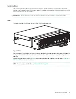
Pictorial views of the supported DDIC with LFF drive are provided below. Modules are shown oriented for
insertion into drive slots located on the enclosure top panel.
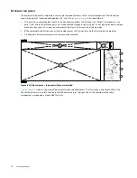
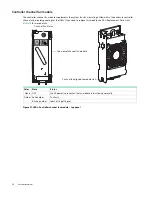
Figure 19 LEDs: Dual path LFF 3.5" drive carrier modules – top panel
If you need to replace this module, see FRU Replacement Time Limit (
) for more details. For additional information
about LFF drive LED behavior, see
NOTE:
Pictorial views of the supported DDIC with SFF drive and adapter are provided below. Modules are shown
oriented for insertion into drive slots located on the enclosure top panel.
LED
Description
Color
State
Definition
1
Not used
N/A
OFF
Not applicable.
2
Fault or
Identify
Amber
OFF
The Disc Drive in Carrier is operating normally.
Solid Amber
A fault has been detected or a service action is required.
Amber 1s on / 1s off
Application requested identification.
Amber - 3s on / 1s off
See log for fault conditions.
1
2
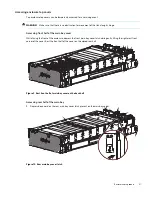
Top view of LFF drive module
DDIC aligned to module slot


