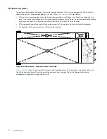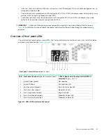
Overview of top panel LEDs
31
Overview of top panel LEDs
To view LEDs of components that are accessible from the main Bay & auxiliary bay covers, you must first open the
respective bay cover in which the component is installed. The enclosure top panel is shown in
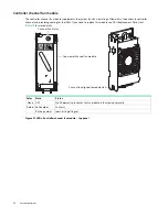
Drive carrier module
The drive carrier module comprises a hard drive held by a carrier.
•
Each 4U106 drive slot can hold a single low profile (1.0-inch) 3.5-inch form factor drive in its carrier.
•
Each 4U106 drive slot can hold a single low profile (5/8-inch) 2.5-inch form factor drive with adapter in its carrier.
•
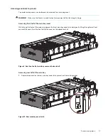
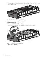
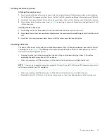
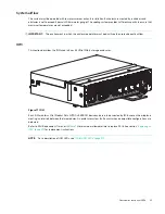
The drive modules are inserted into vertically aligned slots that are accessible from the top of the enclosure. While
facing the front of the enclosure, properly orient the drive module for insertion into the slot:
Hold the module so that the front is facing you (latch tab on left, and drive PCB facing up).
Revolve the module -90º about the horizontal axis (latch is facing up, module is standing on end)
Revolve the module 90º about the vertical axis (latch is facing up, drive PCB is facing left).
The carriers support:
•
Qualified SAS drives (LFF/SFF).
•
Qualified SATA drives (LFF/SFF).
•
Qualified SSDs (SFF).
A plastic casing holds and provides protection for each drive. The drive with protective casing is known as a drive
module. The front cap also has an ergonomic handle that gives the following functions:
•
Secure location of the carrier into and out of drive slots.
•
Positive spring-loading of the drive/midplane connector.


