


Field Service Procedure – Replacement Pol Pot Kit, 4012
Page
3
of
16
Document No
136829 Rev A
Copyright © Sea Tel, Inc 2012 - The information contained in this document is proprietary to Sea
Tel, Inc. This document may not be reproduced or distributed in any form without prior written
consent of Sea Tel, Inc.
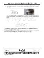
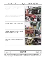
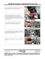
View
the
feed
horn
and
verify
that
the
alignment
pins
of
the
phase
card
are
aligned
vertically
(on
the
top
and
bottom
of
the
feed
horn)
you
should
also
notice
the
tam
mounting
screws
are
parallel
with
each
other
as
shown
below…
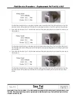
Any
error
in
alignment
is
an
indication
that
the
pol
pot
is
not
correctly
calibrated.
However
a
small
amount
of
error
could
be
calibrated
out
by
using
the
linear
offset
setting
(to
electronically
adjust
the
pol
postion).
If
it’s
deemed
there
is
a
large
amount
of
error
then
calibrating
the
pol
pot
will
be
required
as
per
Fig.
22
to
Fig.
27
in
section
8
of
this
document.
If
no
drive
was
issued
the
function
of
the
24VDC
polang
motor
should
be
verified
as
per
section
7
of
this
document.
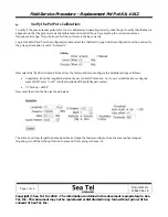
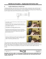
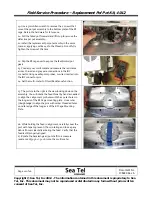
5.
Verify
the
Feed
Assemblies
Range
of
Motion:
To
verify
if
the
4012
antennas
polarity
function
is
calibrated
correctly
refer
to
section
3
of
this
document.
Once
verified
that
the
pot
is
calibrated
the
next
step
will
be
to
verify
that
the
system
has
the
full
range
of
motion
(135
degrees
of
physical
rotation),
verifying
that
the
pol
pot
is
outputting
the
correct
resistance
through
its
range
and
also
that
the
pol
motor
is
driving
the
assembly
correctly.
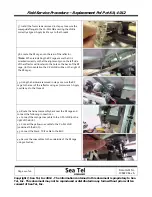
1.
To
verify
the
range
of
motion
on
the
feed
assembly
enter
into
the
“Reflector”
screen
under
the
configuration
options
and
set
the
polang
drive
mode
to
manual
and
click
the
save
button.
This
will
now
give
you
the
ability
to
manually
drive
the
pol
as
opposed
to
the
feed
automatically
aligning
itself
based
on
the
vessels
GPS
location
and
the
look
angle
to
the
desired
satellite.
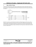
2.
Now
enter
into
the
“Position
Antenna”
screen
from
the
tools
menu
and
enter
the
value
“
‐
90.0”
into
the
linear
window
of
the
polang
target
option
and
press
the
enter
key
on
the
keyboard.
Содержание 4012
Страница 1: ......